Air injection assembly of surgical instrument and puncture outfit
A surgical instrument and gas injection technology, applied in the field of medical equipment, can solve the problems of increased cost, occupation of surgical space, waste of resources, etc., and achieve the effects of simple structure and manufacturing process, favorable for surgical operation, and reduction of surgical space
- Summary
- Abstract
- Description
- Claims
- Application Information
AI Technical Summary
Problems solved by technology
Method used
Image

Examples
Embodiment 1
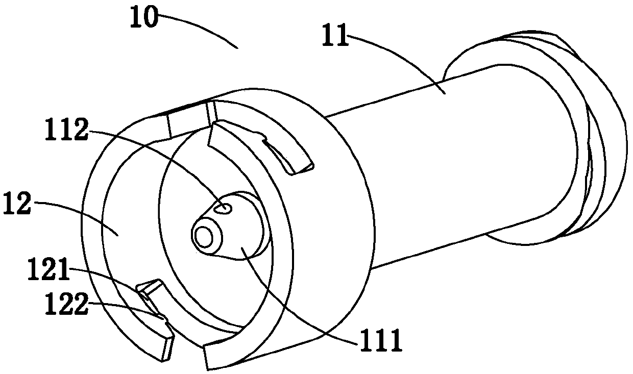
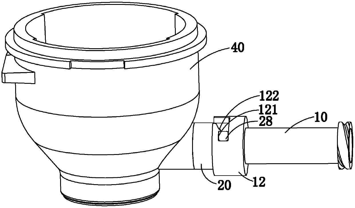
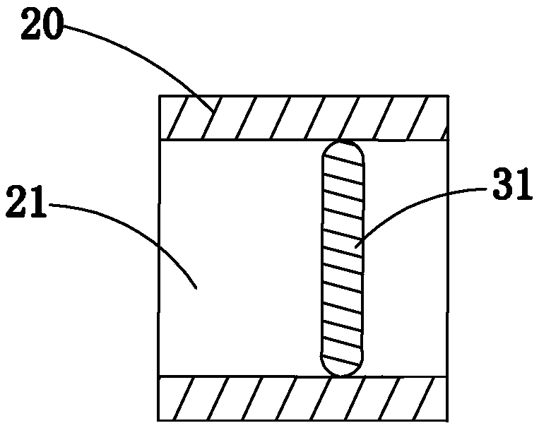
[0039] The sealing member 30 in this embodiment is a sealing block 31 made of elastic material. see image 3 , in the initial state, the sealing block 31 is arranged laterally in the ventilation passage 21 in the ventilation part 20, and there is an interference fit between the sealing block 31 and the ventilation passage 21, that is, all edges of the sealing block 31 fully abut against the ventilation part 20 to seal the vent passage 21. The transverse direction is a direction perpendicular to the axial direction of the air passage 21 . see Figure 4 , when the gas injection part 10 is installed on the ventilation part 20, the gas outlet end 111 of the gas injection pipe 11 exerts a thrust on the part of the sealing block 31, so that the sealing block 31 produces elastic deformation, and the gap between the sealing block 31 and the inner wall of the ventilation part 20 A gap is formed so that the gas injection channel 113 in the gas injection tube 11 communicates with the ven
Embodiment 2
[0041] The sealing member 30 in this embodiment includes a sealing block 31 and an elastic member 32, the sealing block 31 is made of non-elastic material, the elastic member 32 is preferably a shrapnel, and the outer diameter of the sealing block 31 is equal to or slightly larger than the inner diameter of the ventilation member 20, One end of the elastic member 32 is fixed on the wall of the ventilation channel 21 , and the other end of the elastic member 32 is connected with the sealing block 31 . see Figure 5 , in the initial state, under the action of the elastic member 32 , the sealing block 31 is arranged laterally in the air passage 21 to seal the air passage 21 . see Figure 6 , when the gas injection part 10 is installed on the ventilation part 20, the gas outlet end 111 of the gas injection pipe 11 exerts a thrust on the sealing part 30, so that the elastic part 32 produces elastic deformation, and drives the sealing block 31 to rotate, so that the sealing block 31 i
Embodiment 3
[0043] see Figure 7 , the breather 20 in this embodiment includes a first breather 22 and a second breather 23, the second breather 23 is partly located in the first breather 22, and the second stopper 25 is a protrusion formed on the second One end of the ventilation element 23 is located in the first ventilation element 22 . The first stop portion 24 is arranged at one end of the first breather 22 and is arranged in a ring shape, and the middle opening of the ring is for the gas outlet end 111 of the gas injection tube 11 to pass through. A ventilation channel 21 is provided in the first ventilation part 22 , and a ventilation channel 21 is also provided in the second ventilation part 23 . Both the second stopper portion 25 and the sealing member 30 are disposed in the ventilation channel 21 of the first ventilation member 22 . The ventilation channel 21 in the second ventilation part 23 communicates with the inner cavity of the casing storehouse 40 .
[0044] see Figure
PUM
 Abstract
Description
Claims
Application Information
 - R&D Engineer
- R&D Manager
- IP Professional
- Industry Leading Data Capabilities
- Powerful AI technology
- Patent DNA Extraction
Browse by: Latest US Patents, China's latest patents, Technical Efficacy Thesaurus, Application Domain, Technology Topic.
© 2024 PatSnap. All rights reserved.Legal|Privacy policy|Modern Slavery Act Transparency Statement|Sitemap