Automobile A-pillar manufacturing method

A manufacturing method and automobile technology, applied to vehicle components, superstructures, subassemblies of superstructures, etc., can solve the problems of enlarging the driver's blind spot, high cost, and enlarged cross-sectional area, so as to reduce the blind spot of vision and lighten the Weight, driving safety improvement effect

Inactive Publication Date: 2020-04-10
YANSHAN UNIV
View PDF7 Cites 0 Cited by
  • Summary
  • Abstract
  • Description
  • Claims
  • Application Information

AI Technical Summary

Problems solved by technology

The A-pillar is a structure that directly affects the driver. According to the current technical level, most of them use high-strength alloy materials and increase the cross-sectional area to increase the strength of the supporting pillars. However, the cost

Method used


Image

  • Automobile A-pillar manufacturing method
  • Automobile A-pillar manufacturing method
  • Automobile A-pillar manufacturing method

Examples


Embodiment Construction

[0020] Below in conjunction with accompanying drawing and specific embodiment the present invention is described in further detail:

[0021] The invention relates to a method for manufacturing an automobile A-pillar. Firstly, the structure of the automobile A-pillar is improved, and then the processing and manufacturing method of the automobile A-pillar is further disclosed.

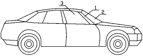
[0022] like figure 1 Shown is a schematic diagram of a car, which includes a car A-pillar 1, a front windshield 2 and a side windshield 3. Both the windshield 2 and the side windshield 3 need the A-pillar 1 of the automobile to be clamped and fixed. The A-pillar 1 of the automobile includes a frame and a transparent glass material 10 embedded in the frame.

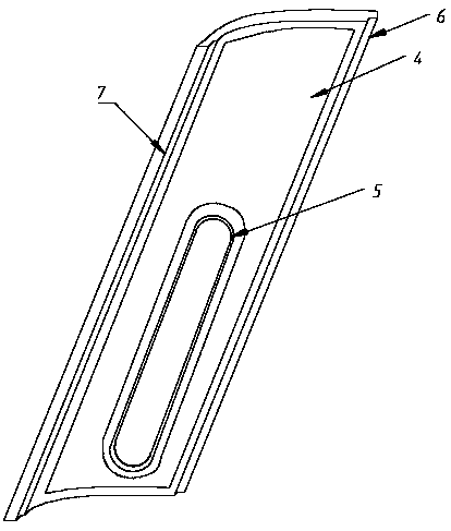
[0023] like figure 2 , image 3 , Figure 4 As shown, the framework of the automobile A-pillar 1 in the present invention includes the automobile A-pillar outer part 4 and the automobile A-pillar inner part 8 . The outer part 4 of the A-pillar of


PUM


Abstract

The invention relates to an automobile A-pillar manufacturing method, and belongs to the technical field of automobile body structure design. The automobile A-pillar comprises a framework, a U-shapedclamping groove is formed in the edge of the framework, a transparent glass material is installed in the middle of the framework, and the framework is connected with the transparent glass material through an annular clamping groove. The framework is divided into an automobile A-pillar inner part and an automobile A-pillar outer part, and the automobile A-pillar inner part and the automobile A-pillar outer part are welded into a whole through a plasma arc welding method. An aluminum alloy material is adopted, so that the weight can be reduced under the condition that the strength of the automobile A-pillar is met. The two parts of the automobile A-pillar can achieve the effect of one-side welding and two-side forming through the plasma arc welding technology, and compared with existing common electric resistance welding, the welding seam is attractive, and the welding effect is good. A polariscope is selected as the transparent glass material, the view blind area caused by the automobile A-pillar is effectively reduced, meanwhile, the sight is not disturbed in the linear driving process, and the driving safety is improved.

Description


Claims


Application Information

Patent Timeline
Owner YANSHAN UNIV
Why Eureka
Try Eureka