Motor vehicle emission factor calculation method based on urban tunnel
A technology of emission factor and calculation method, which is applied in the direction of calculation, complex mathematical operations, instruments, etc., can solve the problem of motor vehicle emission, such as the difficulty in obtaining the emission factor of motor vehicles, and achieve the effect of obtaining
- Summary
- Abstract
- Description
- Claims
- Application Information
AI Technical Summary
Problems solved by technology
Method used
Image


Examples
Embodiment 1
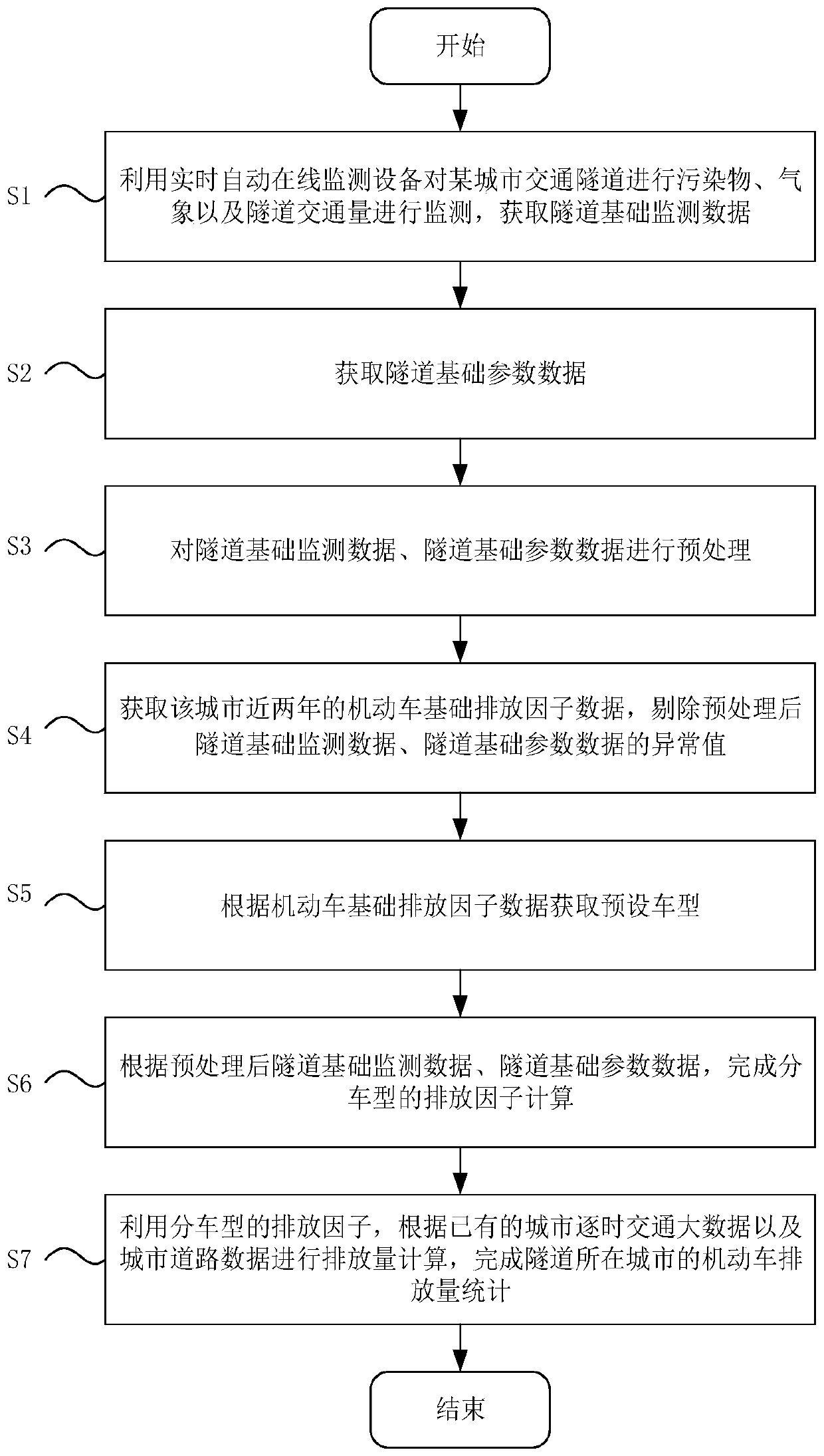
[0063] Such as figure 1 As shown, the calculation method of motor vehicle emission factors based on urban tunnels includes the following steps:
[0064] S1: Use real-time automatic online monitoring equipment to monitor pollutants, weather and tunnel traffic volume in a certain urban traffic tunnel, and obtain tunnel basic monitoring data;
[0065] S2: Obtain the basic parameter data of the tunnel;
[0066] S3: Preprocessing the tunnel foundation monitoring data and tunnel foundation parameter data;
[0067] S4: Obtain the basic motor vehicle emission factor data of the city in the past two years, and eliminate the outliers in the tunnel basic monitoring data and tunnel basic parameter data after preprocessing;
[0068] S5: Acquire preset vehicle models according to the basic emission factor data of motor vehicles;
[0069] S6: According to the preprocessed tunnel foundation monitoring data and tunnel foundation parameter data, complete the calculation of emission factors by v
Embodiment 2
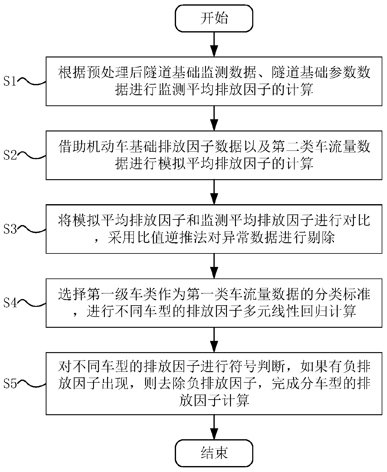
[0086] More specifically, on the basis of Example 1, such as figure 2 As shown, the step S6 specifically includes the following steps:
[0087] S61: Calculate the monitoring average emission factor according to the preprocessed tunnel foundation monitoring data and tunnel foundation parameter data, the specific expression is:
[0088]
[0089] Among them, EF t To monitor the average emission factor [g·(km·vehicle) -1 ]; ΔC is the difference of pollutant concentration between monitoring points (mg m -3 ); A is the average cross-sectional area of the tunnel mouth (m 2 ); u is the tunnel average wind speed (m·s -1 ); N is the total traffic volume passing through the tunnel during the sampling period (vehicle s -1 ); L is the distance between two sampling points in the tunnel (m);
[0090] S62: Calculate the simulated average emission factor with the help of the basic emission factor data of motor vehicles and the second-class traffic flow data, the specific expression is
Embodiment 3
[0110] More specifically, on the basis of Embodiment 1 and Embodiment 2, the emission factor calculation method provided by the embodiment of the present invention is further described by taking Guangzhou City as an example.
[0111] In this embodiment, from October 26 to November 1, 2012, real-time automatic online monitoring equipment was used to monitor the pollutants, weather and tunnel traffic volume of the Pearl River Tunnel in Guangzhou City. The automatic online monitoring was placed at the entrance and exit of the tunnel, and the main monitoring Objects: pollutant concentration at the entrance and exit (mainly NOx, CO), wind speed, temperature, pressure, and traffic flow. The monitoring equipment produces data every five minutes and monitors 24 hours a day.
[0112] Obtain the basic motor vehicle emission factor data of the city in similar years. The basic motor vehicle emission factor data is shown in the following table (unit: g·(km·vehicle) -1 ):
[0113] Motor Vehi
PUM
 Abstract
Description
Claims
Application Information
 - R&D Engineer
- R&D Manager
- IP Professional
- Industry Leading Data Capabilities
- Powerful AI technology
- Patent DNA Extraction
Browse by: Latest US Patents, China's latest patents, Technical Efficacy Thesaurus, Application Domain, Technology Topic.
© 2024 PatSnap. All rights reserved.Legal|Privacy policy|Modern Slavery Act Transparency Statement|Sitemap