Stator for dynamo-electric machine
A technology for rotating electrical machines and stators, applied in the field of stators, can solve the problems of unstable coil height and reduced insulation reliability, and achieve the effect of improving insulation reliability and ensuring the insulation distance along the surface.
- Summary
- Abstract
- Description
- Claims
- Application Information
AI Technical Summary
Problems solved by technology
Method used
Image

Examples
Example Embodiment
[0026] Example 1
[0027] Below, refer to Figure 1~Figure 8 Example 1 of the present invention will be described.
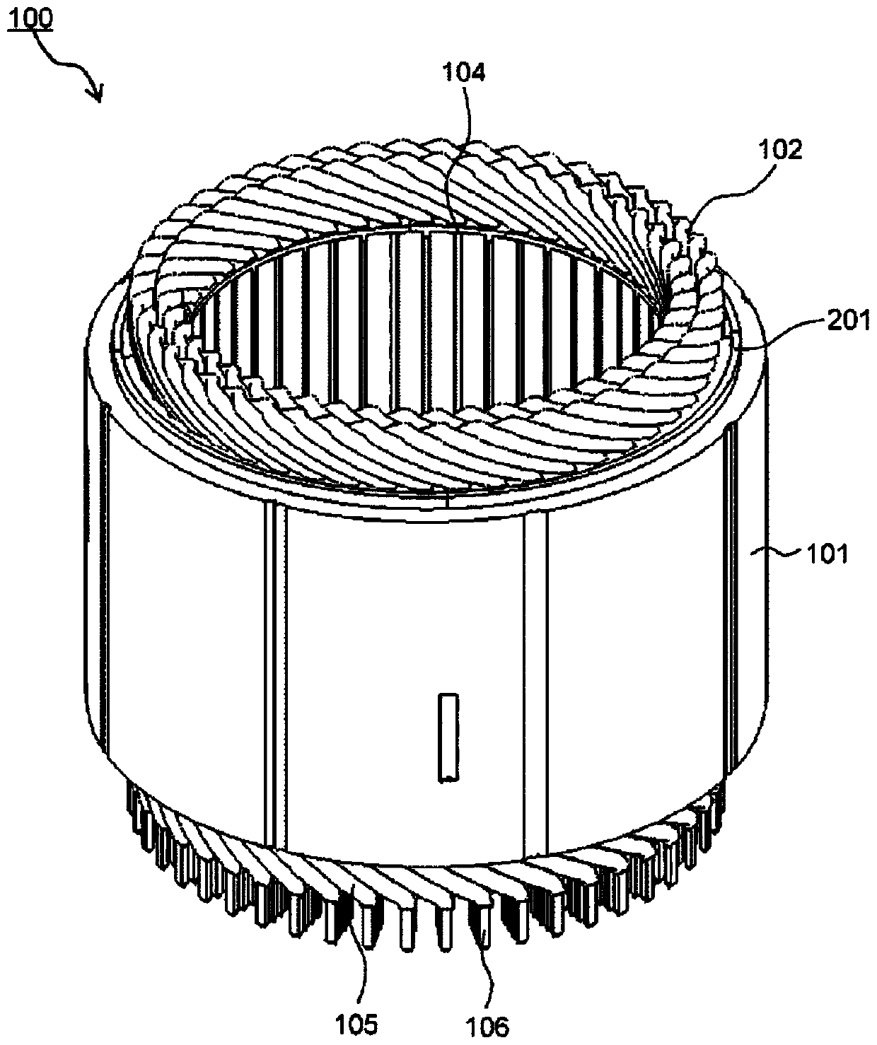
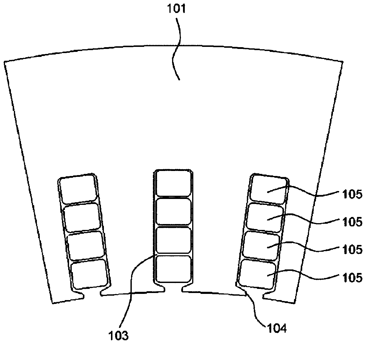
[0028] figure 1 It is a perspective view showing the stator of the rotating electric machine in Example 1 of the present invention as a single body. figure 2 This is a cross-sectional view (horizontal cross-sectional view) of the main part of the stator core in Embodiment 1 of the present invention, and is a cross-sectional view corresponding to the inside of each slot 103.
[0029] Such as figure 1 and figure 2 As shown, the stator 100 of the rotating electric machine has: a stator core (also referred to as a stator core) 101 having a plurality of slots 103 formed on the inner circumference side, and a U-phase, V-phase, and W-phase wound on the stator core 101. The corresponding three stator windings (also referred to as segment coils) 102 and a coil support member 201 supporting each stator winding 102. The stator core 101 is formed of a cylindrical cylindrical body
Example Embodiment
[0039] Example 2
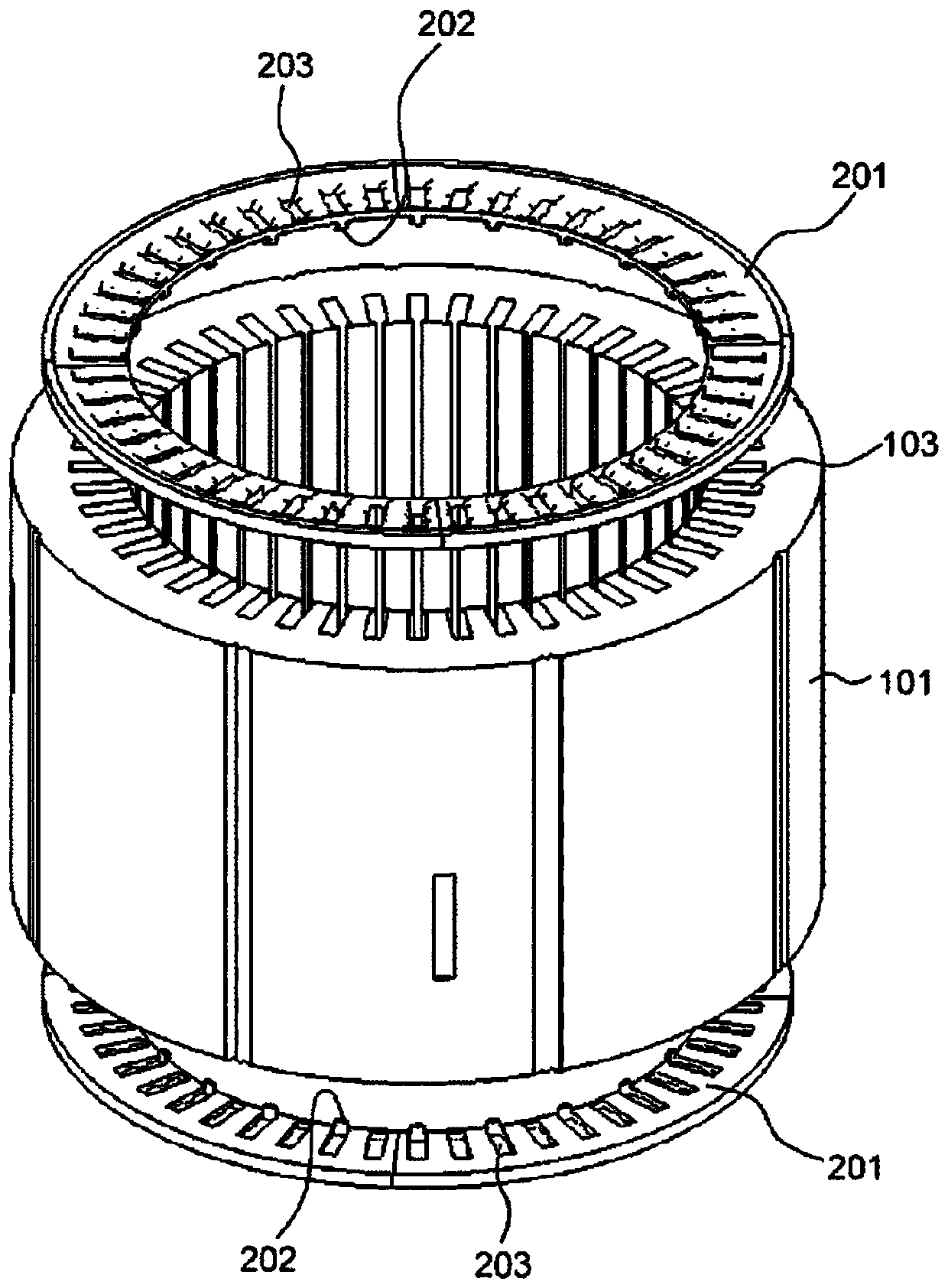
[0040] Figure 7 It is a perspective view of the split type coil support member in Example 2, (a) is a top view, (b) is a bottom view. In the second embodiment, the split-type coil support member 201B is used instead of the split-type coil support member 201A. The other structure is the same as that of the first embodiment, and the description thereof is omitted.
[0041] The split-type coil support member 201B is configured as an arc-shaped member obtained by dividing the coil support member 201 formed in an annular shape (ring shape) into four parts in the circumferential direction. By combining four split type coil support members 201B in the circumferential direction, an annular coil support member 201 is formed. In the split type coil support member 201B, a plurality of through holes (holes) 203 are formed at equal intervals in the circumferential direction. The through holes 203 are openings connected to the slots 103 for inserting the stator winding 102 (coi
Example Embodiment
[0043] Example 3
[0044] Figure 8 It is an exploded perspective view of the split type coil support member in Example 3. In the third embodiment, the split-type coil support members 201C and D are used in combination instead of the split-type coil support member 201A. The other structures are the same as in the first embodiment, and their descriptions are omitted.
[0045] The split-type coil support members 201C, D are configured as a member obtained by dividing an arc-shaped member into two parts in the radial direction, and the arc-shaped member is the coil support member 201 formed into an annular (ring) shape. It is divided into 4 parts in the circumferential direction. By combining the split-type coil support member 201C and the split-type coil support member D, and the combined split-type coil support member 201C and the split-type coil support member D are combined in four in the circumferential direction to form a ring-shaped coil support Component 201.
[0046] The split-
PUM
 Abstract
Description
Claims
Application Information
 - R&D Engineer
- R&D Manager
- IP Professional
- Industry Leading Data Capabilities
- Powerful AI technology
- Patent DNA Extraction
Browse by: Latest US Patents, China's latest patents, Technical Efficacy Thesaurus, Application Domain, Technology Topic.
© 2024 PatSnap. All rights reserved.Legal|Privacy policy|Modern Slavery Act Transparency Statement|Sitemap