Device and method for flashing BMC Flash

A technology of an input device and a display device, applied in the computer field, can solve the problems of increasing the risk of flashing, failure of BMC to start, and failure of the BMC to start, so as to reduce the risk of flashing errors and improve the efficiency of flashing.

Inactive Publication Date: 2020-07-03
SUZHOU LANGCHAO INTELLIGENT TECH CO LTD
View PDF0 Cites 0 Cited by
  • Summary
  • Abstract
  • Description
  • Claims
  • Application Information

AI Technical Summary

Benefits of technology

This technology allows for automatic flashings on different types of devices without requiring manual interventions or adjustments during commissioned testing. It uses special software that can be installed onto these systems' memory cards instead of manually entering new data into them when they are being tested. Overall, its benefits include improved performance and reduced risks associated therewith while still ensuring consistently high quality results.

Problems solved by technology

This patented technology solves this issue with traditional methods used during manufacturing where workers have had difficulty understanding or adjusting the way they work around issues caused by poorly designed components like BMCI due to environmental factors affecting their performance over time.

Method used


Image

  • Device and method for flashing BMC Flash
  • Device and method for flashing BMC Flash

Examples


Embodiment Construction

[0031] The core of the present invention is to provide a device for flashing BMC Flash, which reduces the risk of flashing errors and is also conducive to improving flashing efficiency.

[0032] In order to enable those skilled in the art to better understand the solution of the present invention, the present invention will be further described in detail below in conjunction with the accompanying drawings and specific embodiments. Apparently, the described embodiments are only some of the embodiments of the present invention, but not all of them. Based on the embodiments of the present invention, all other embodiments obtained by persons of ordinary skill in the art without making creative efforts belong to the protection scope of the present invention.

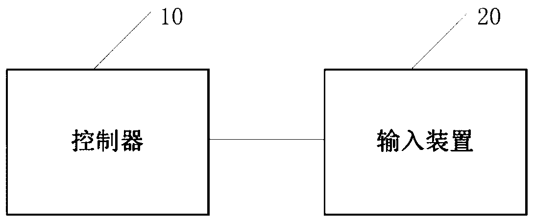
[0033] Please refer to figure 1 , figure 1 It is a structural schematic diagram of a device for brushing BMC Flash among the present invention, and the device for brushing BMC Flash can include:

[0034] The controller 10 is


PUM


Abstract

The invention discloses a device for flashing BMC Flash, and the device comprises a controller which is used for being in communication connection with a configuration server, and obtaining Flash firmware corresponding to a code from the configuration server according to the preset code; when a trigger signal sent by the input device is received, the obtained Flash firmware is flashed into Flash of a BMC connected with the controller; and the input device is connected with the controller. By applying the technical scheme provided by the embodiment of the invention, the risk of flashing errorsis reduced, the flashing efficiency is favorably improved, and the invention further provides a method for flashing the BMC Flash, which has corresponding technical effects.

Description


Claims


Application Information

Patent Timeline
Owner SUZHOU LANGCHAO INTELLIGENT TECH CO LTD
Why Eureka
Try Eureka