Acoustic coupling structure of in-ear earphone cavity
An in-ear, acoustic coupling technology, applied in earpiece/earphone accessories, internal auditory earphones, microphones, etc., can solve the problems of harsh human voice, occasional screaming, sound quality bottleneck of in-ear earphones, etc., to reduce high-frequency resonance peak effect
- Summary
- Abstract
- Description
- Claims
- Application Information
AI Technical Summary
Problems solved by technology
Method used
Image

Examples
Embodiment 1
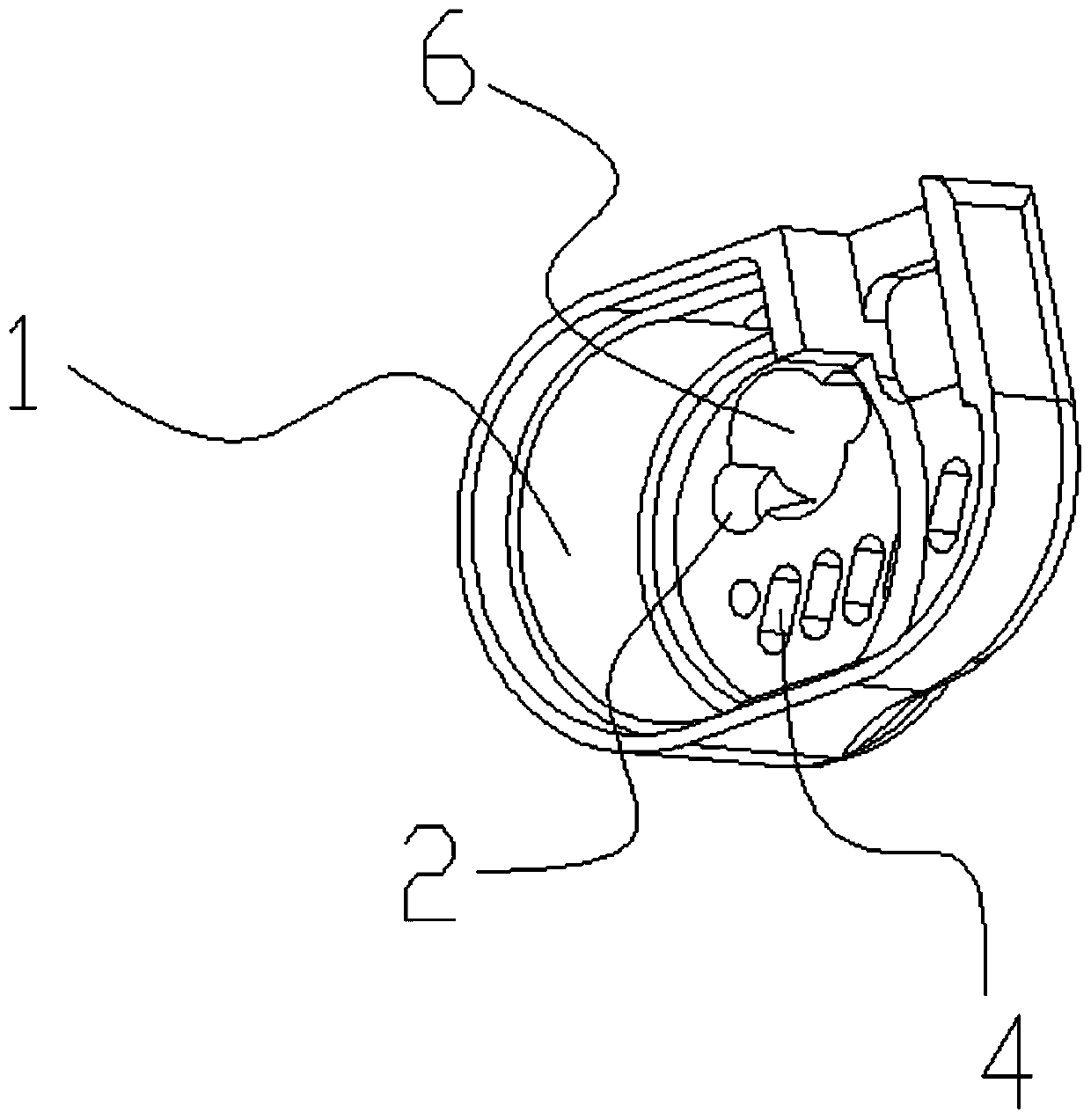
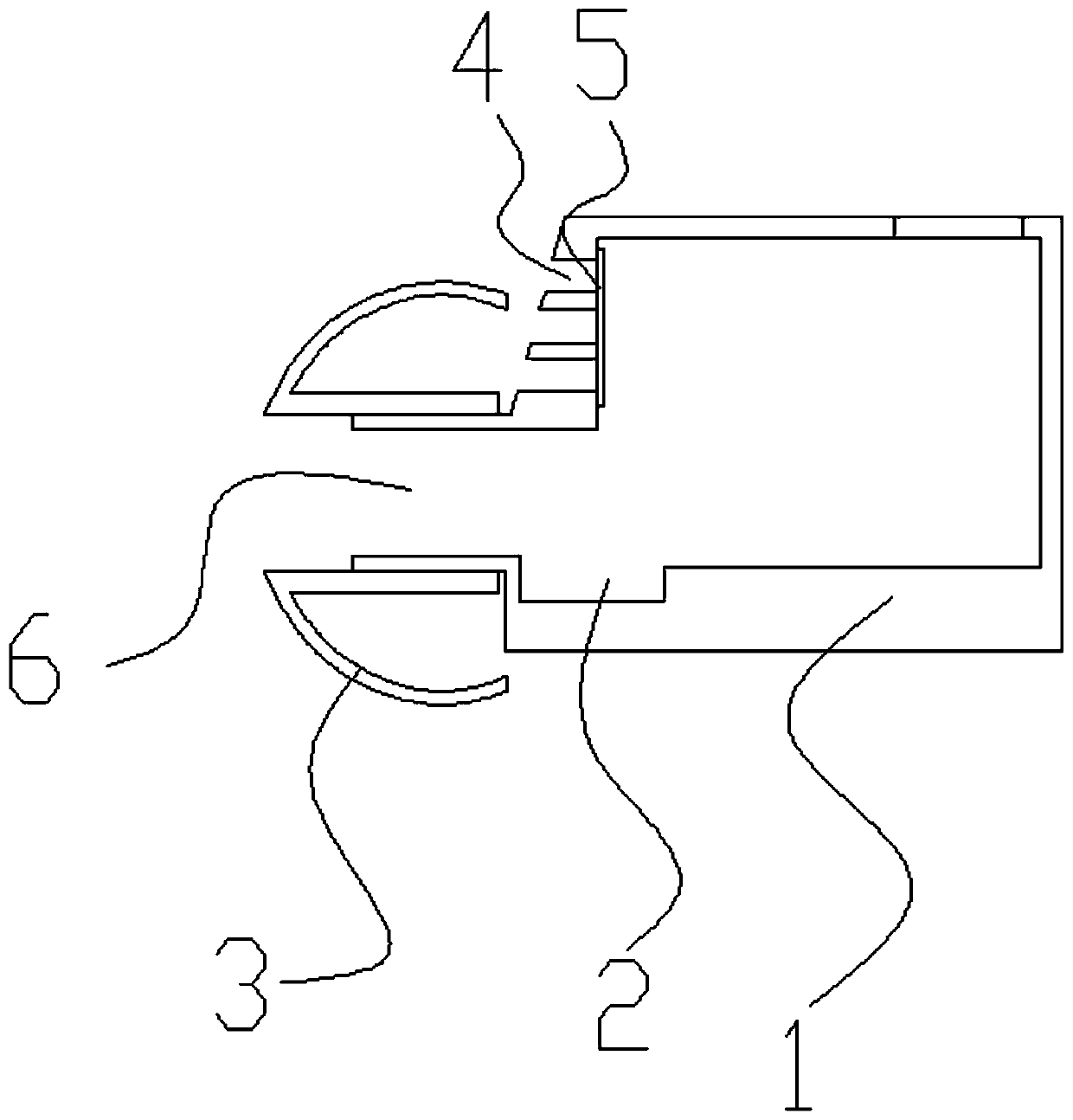
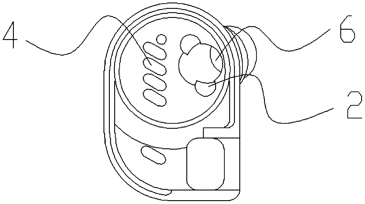
[0032] Such as Figure 1-4 As shown, an acoustic coupling structure of an in-ear earphone cavity includes an earphone housing 1, a coupling cavity 2 is provided on the side wall of the sound conduit 6 of the earphone housing 1, and the coupling cavity 2 is located on the acoustic tube 6. The end of the conduit 6 away from the silicone sleeve 3 of the in-ear earphone, the side wall of the earphone housing 1 is also provided with a pressure relief through hole 4 , and the inside of the pressure relief through hole 4 is provided with a damping member 5 .
[0033] Based on the principle of Helmholtz resonance (Helmholtz resonance), a coupling cavity 2 with a low quality factor (Q value) is drawn out of the inner wall of the sound conduit 6, and the high Q value resonance peak of 5-6kHz is offset by anti-phase resonance; it is located in the earphone shell The side wall of the front cavity of 1 is provided with a pressure relief through hole 4, which performs high-pass filtering in a
Embodiment 2
[0035] Such as Figure 1-4 As shown, in this embodiment, on the basis of Embodiment 1, there are two coupling cavities 2, which are symmetrically arranged on opposite side walls of the sound conduit 6 .
[0036] There are two coupling cavities 2, and the two coupling cavities 2 are arranged symmetrically for the convenience of realizing resonance.
Embodiment 3
[0038] Such as Figure 1-4 As shown, in this embodiment, on the basis of Embodiment 1 or 2, the coupling cavity 2 is cylindrical, one side of the coupling cavity 2 communicates with the sound conduit 6, and the axis of the coupling cavity 2 is connected to the The axes of the sound conduit 6 are parallel.
[0039] The coupling cavity 2 is arranged in a cylindrical shape, and the axis of the coupling cavity 2 is parallel to the axis of the sound conduit 6, because it facilitates CNC machining.
PUM
 Abstract
Description
Claims
Application Information
 - R&D Engineer
- R&D Manager
- IP Professional
- Industry Leading Data Capabilities
- Powerful AI technology
- Patent DNA Extraction
Browse by: Latest US Patents, China's latest patents, Technical Efficacy Thesaurus, Application Domain, Technology Topic.
© 2024 PatSnap. All rights reserved.Legal|Privacy policy|Modern Slavery Act Transparency Statement|Sitemap