L-shaped pitot tube capable of being straightened

A pitot tube and L-shaped technology, which is applied in the field of wind speed and air volume testing in the pipeline, and can solve problems such as measuring flow speed

Pending Publication Date: 2020-08-04
HUANENG CLEAN ENERGY RES INST +1
View PDF0 Cites 0 Cited by
  • Summary
  • Abstract
  • Description
  • Claims
  • Application Information

AI Technical Summary

Benefits of technology

This patented design allows for flexibility during measurements by allowing an elongated device called a Pitott tubule (a type of liquid level gauge) to pass through different areas on both sides of a pipeline without being blocked up due to its size. It also has features like making sure there's enough space between them to allow fluid to freely move around inside while still keeping accurate readings from outside.

Problems solved by technology

This patented technical problem addressed in this patents relates to finding ways for inserting pneumatic instruments (such as gas meters) without having to open up any holes inside pipelines due to insufficient space available during installation.

Method used


Image

  • L-shaped pitot tube capable of being straightened
  • L-shaped pitot tube capable of being straightened
  • L-shaped pitot tube capable of being straightened

Examples


Embodiment Construction

[0023] The present invention will be described in further detail below in conjunction with the accompanying drawings.

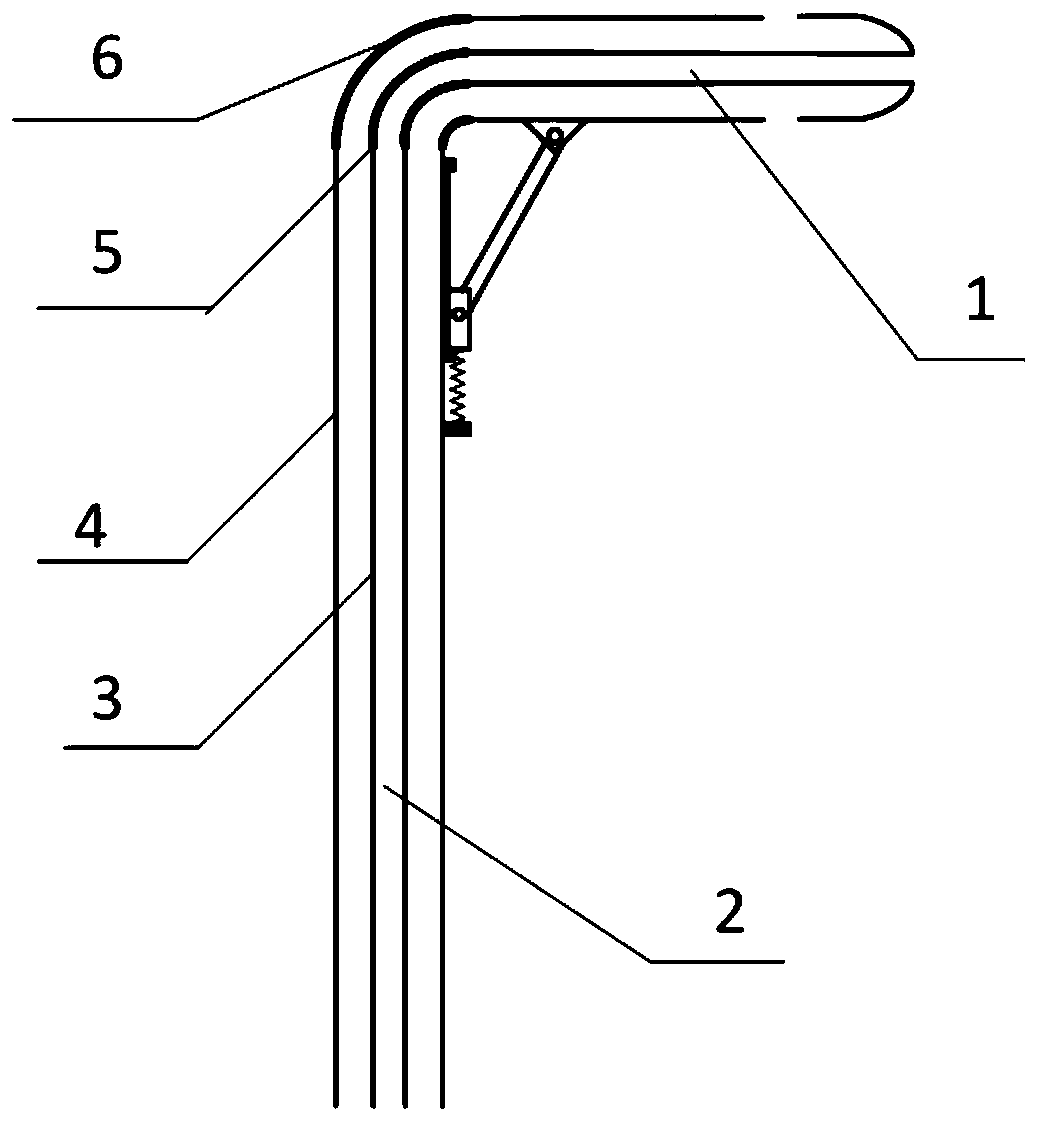
[0024] Such as figure 1 As shown, a kind of straightenable L-shaped Pitot tube provided by the present invention comprises a Pitot tube body, and the Pitot tube body includes a horizontal pipe section and a vertical pipe section, between one end of the horizontal pipe section and one end of the vertical pipe section It is flexibly connected to form an L-shaped structure that can be straightened.

[0025] The horizontal pipe section includes a first outer pipe 1 and a first inner pipe 2 , and the first outer pipe 1 is sleeved on the first inner pipe 2 .

[0026] The vertical pipe section includes a second outer pipe 4 and a second inner pipe 3 , and the second outer pipe 4 is sleeved on the second inner pipe 3 .

[0027] The first outer tube 1 and the second outer tube 4 are flexibly connected to form a straightenable L-shaped structure.

[0028] The first inn


PUM


Abstract

The invention provides an L-shaped pitot tube capable of being straightened. The L-shaped pitot tube comprises a horizontal tube section and a vertical tube section, wherein one end of the horizontaltube section and one end of the vertical tube section are in flexible connection to form an L-shaped structure capable of being straightened. When the connecting pipe is too long or the area of a measuring hand hole is too small, the pitot tube is adjusted to be of a 1-shaped structure, and when a normal test experiment is conducted, the pitot tube is reset to be in an L shape, and measurement ofairflow total pressure and static pressure is completed. Therefore, the problem that when the connecting pipe is too long or the area of the measuring hand hole is too small, the L-shaped pitot tube cannot be inserted into the pipeline through the measuring hand hole to measure the flow velocity can be well solved.

Description


Claims


Application Information

Patent Timeline
Owner HUANENG CLEAN ENERGY RES INST
Why Eureka
Try Eureka