Method for suppressing mutual correlation interference of terahertz scanning imaging equipment
A scanning imaging device and terahertz technology, applied in the field of scanning imaging, can solve the problems of image filtering and noise reduction algorithm interference, affecting the detection effect, etc., and achieve the effect of suppressing mutual interference
- Summary
- Abstract
- Description
- Claims
- Application Information
AI Technical Summary
Problems solved by technology
Method used
Image

Examples
Embodiment approach 1
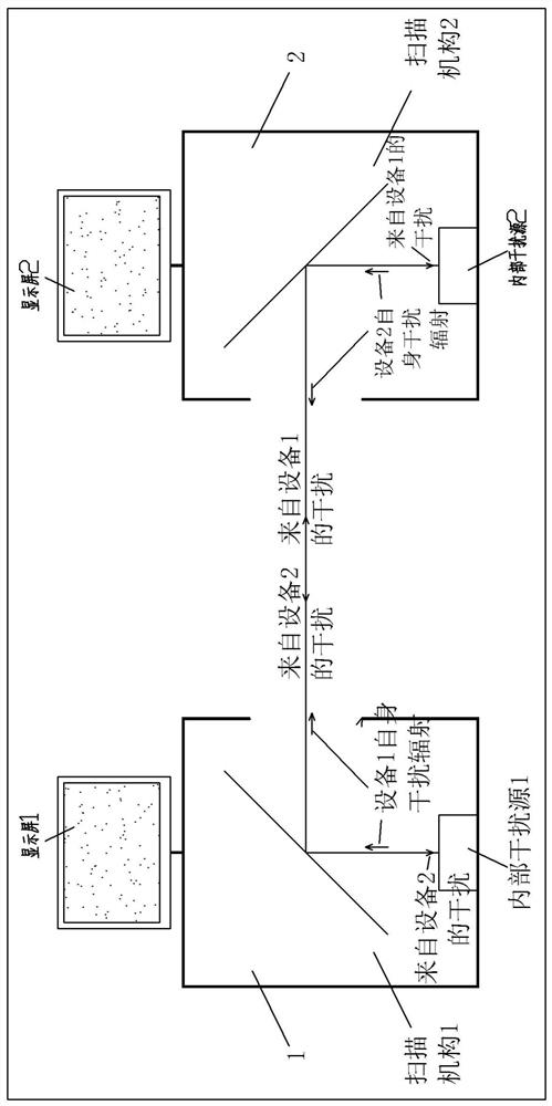
[0040] Specific implementation method one, see Picture 9 : A main controller is used to control the respective movements of the scanning mechanisms of the two devices, and the scanning mechanism control signal sent by the main controller to one of the first devices 1 is used as the reference control signal to make the first light output by the first device 1 The swing angle of the shaft 111 is used as the reference angle; the scanning mechanism control signal sent by the main controller to the second device 2 is used as the bias control signal to make the swing angle of the second optical axis 211 output by the second device 2 lead or lag behind the reference angle by 0.25 t;
[0041] When a main controller controls the respective movements of the scanners of two devices, the two devices are of the same specification and model.
Embodiment approach 2
[0042] Specific implementation method two, see Picture 10 : Use a first device 1 with a built-in main controller and control the movement of its own scanning mechanism as the host, and another second device 2 without a built-in main controller that needs to receive external control signals to control the movement of its scanning mechanism The slave machine uses the signal from the main controller of the first device 1 to control its own scanning mechanism as the reference control signal, and makes the swing angle of the first optical axis 111 output by the first device 1 as the reference angle; sends the main controller of the first device 1 to The control signal of the second device 2 is used as a bias control signal to make the swing angle of the second optical axis 211 output by the second device 2 lead or lag behind the reference angle by 0.25t.
[0043] The working principle is as follows. When the swing angle of the first optical axis of one device is 0°, the swing angle of t
PUM
 Abstract
Description
Claims
Application Information
 - R&D Engineer
- R&D Manager
- IP Professional
- Industry Leading Data Capabilities
- Powerful AI technology
- Patent DNA Extraction
Browse by: Latest US Patents, China's latest patents, Technical Efficacy Thesaurus, Application Domain, Technology Topic.
© 2024 PatSnap. All rights reserved.Legal|Privacy policy|Modern Slavery Act Transparency Statement|Sitemap