Lower limb joint rehabilitation exercise fastening device based on self-constraint

A technology for fastening devices and lower limbs, applied in sports accessories, gymnastics equipment, etc., can solve problems that easily affect patients' emotions, cost, and large medical staff

Inactive Publication Date: 2021-02-26
HUNAN UNIV OF ARTS & SCI
View PDF7 Cites 1 Cited by
  • Summary
  • Abstract
  • Description
  • Claims
  • Application Information

AI Technical Summary

Problems solved by technology

[0003] The existing lower limb rehabilitation exercise devices are generally trained with the assistance of medical staff. This method consumes a lot of medical strength, and at the same time, improper op

Method used


Image

  • Lower limb joint rehabilitation exercise fastening device based on self-constraint
  • Lower limb joint rehabilitation exercise fastening device based on self-constraint
  • Lower limb joint rehabilitation exercise fastening device based on self-constraint

Examples


Embodiment 1

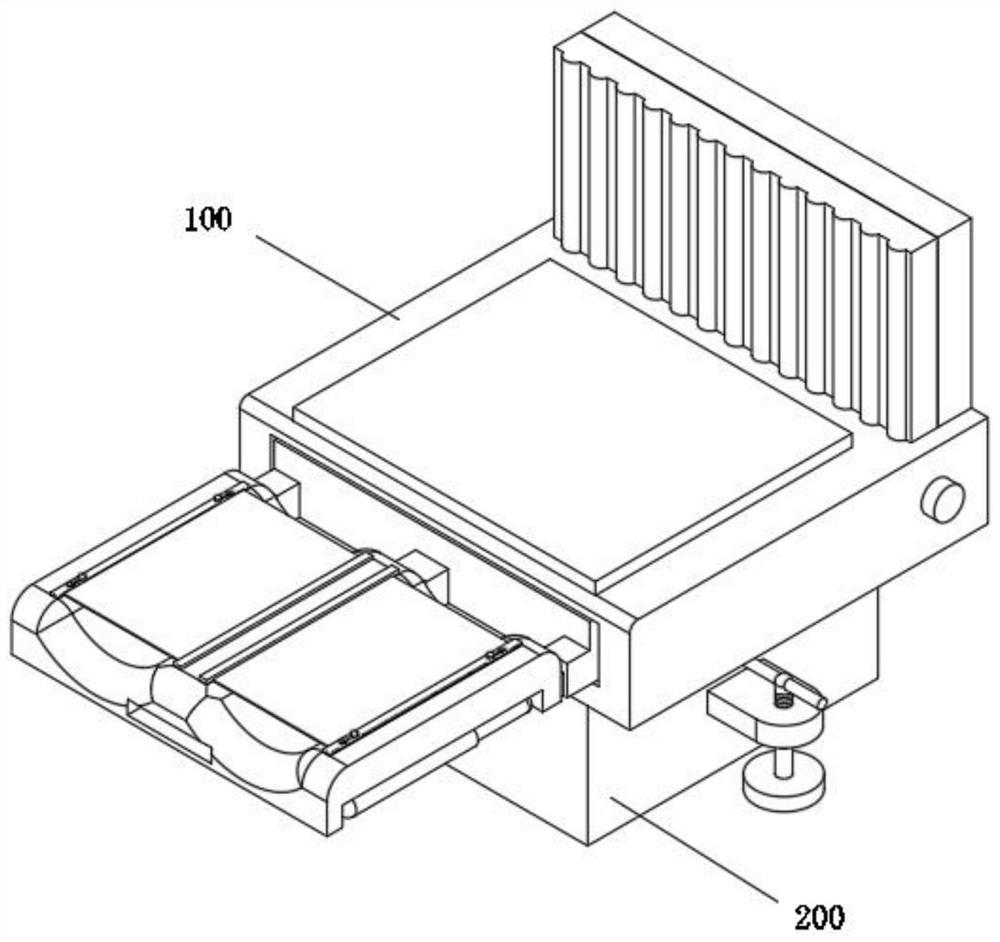
[0054] see Figure 1-Figure 15 As shown, this embodiment provides a self-binding lower limb joint rehabilitation exercise fastening device, including a movable base 200 and a lower limb exercise mechanism 100 installed above the movable base 200, the lower limb exercise mechanism 100 at least includes:

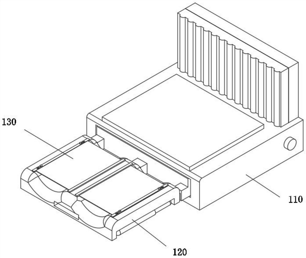
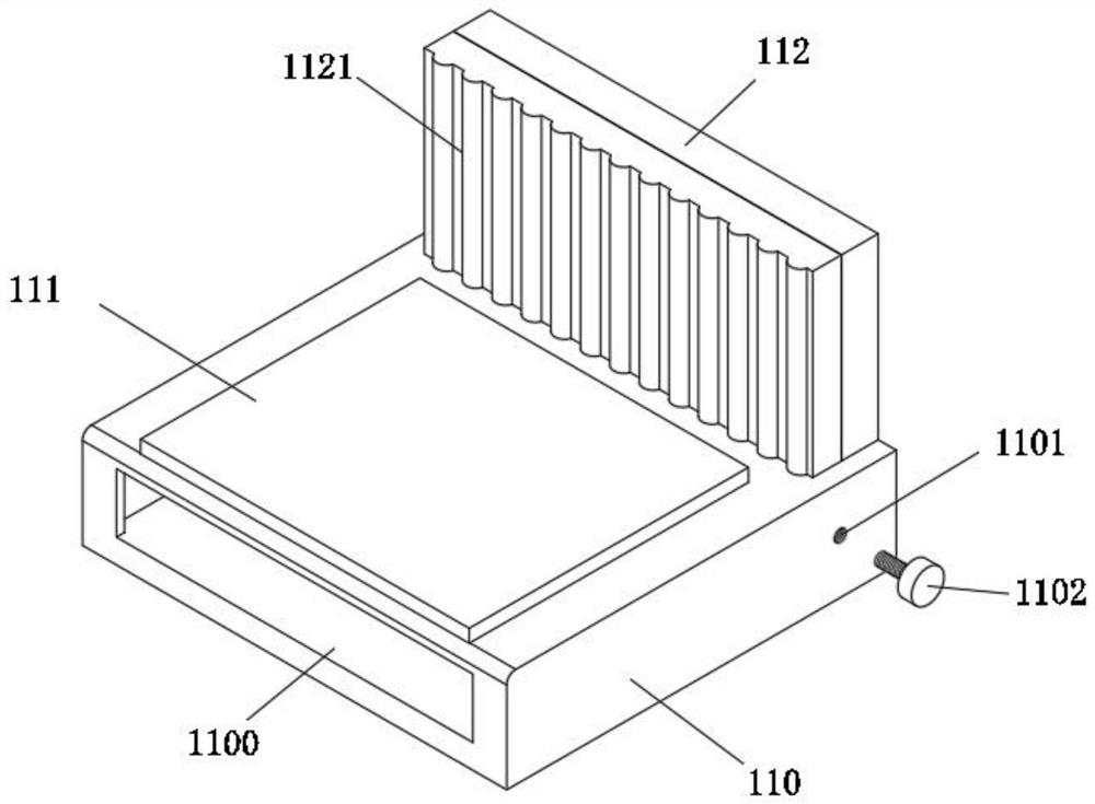
[0055] The base 110, the interior of the base 110 is provided with a sliding cavity 1100, and one end of the upper surface of the base 110 is provided with a backboard 112, which is convenient for the patient to lean on the backboard;

[0056] The exercise device 120 includes a sliding plate 121, the front surface of the sliding plate 121 is provided with a connecting head 1211, a plurality of connecting heads 1211 are provided, a connecting groove 1212 is formed inside the connecting head 1211, and a connecting rod is formed inside the connecting groove 1212 1213, the front side of the sliding plate 121 is connected with a lower limb placing plate 122, the rear surface of the lo


PUM


Abstract

The invention relates to the technical field of lower limb joint rehabilitation, in particular to a lower limb joint rehabilitation exercise fastening device based on self-constraint. The lower limb joint rehabilitation exercise fastening device comprises a moving seat and a lower limb exercise mechanism mounted above the moving seat. In the lower limb joint rehabilitation exercise fastening device, the arranged exercise device is rotatably connected with a connecting rod through rotating holes, a sliding plate and a lower limb placing plate are conveniently connected, and meanwhile, through rotation of the lower limb placing plate, a patient can conveniently exercise the legs, and through the arranged fastening device,fixing strip rods and fixing plates are connected, so that the lower limbs of the patient are stabilized conveniently, and the exercise rehabilitation work of the patient is facilitated.

Description


Claims


Application Information

Patent Timeline
Owner HUNAN UNIV OF ARTS & SCI
Why Eureka
Try Eureka