Closed-loop control device of optometry unit

A closed-loop control and optometry technology, which is applied in the field of optometry, can solve the problems of poor automatic control, inconvenient movement of the optometry head, and low movement accuracy, and achieve good adjustment and control effects, clear and easy-to-understand structure, and simple principles.

Pending Publication Date: 2021-03-16
苏州九思科技有限公司
View PDF0 Cites 0 Cited by
  • Summary
  • Abstract
  • Description
  • Claims
  • Application Information

AI Technical Summary

Problems solved by technology

The optometry head in the traditional optometry is inconvenient to move, the movement accuracy is not high, the automatic contr

Method used


Image

  • Closed-loop control device of optometry unit
  • Closed-loop control device of optometry unit
  • Closed-loop control device of optometry unit

Examples


Embodiment Construction

[0018] The following will clearly and completely describe the technical solutions in the embodiments of the present invention with reference to the accompanying drawings in the embodiments of the present invention. Obviously, the described embodiments are only some, not all, embodiments of the present invention. Based on the embodiments of the present invention, all other embodiments obtained by persons of ordinary skill in the art without making creative efforts belong to the protection scope of the present invention.

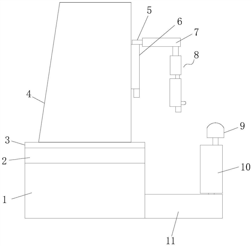
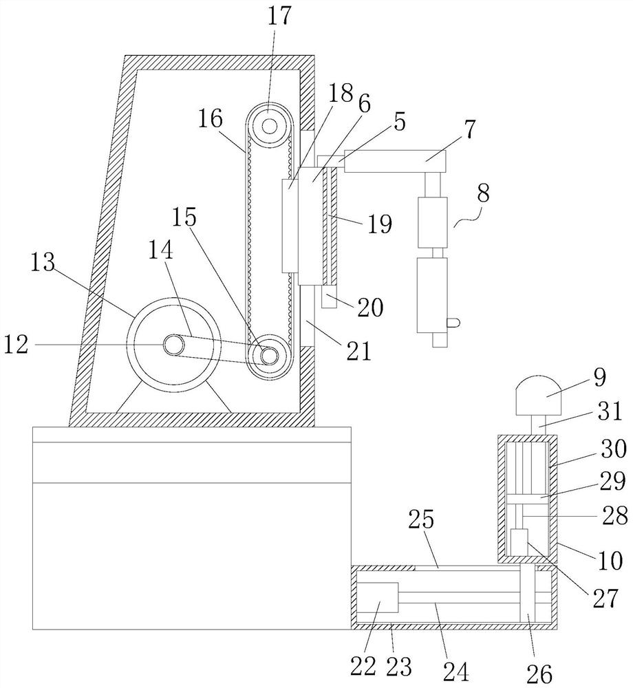
[0019] see Figure 1~3 , the present invention provides a technical solution: a closed-loop control device for optometry, including a base 1, a rectangular frame 2 is fixedly connected to the upper end of the base 1, a bottom plate 3 is arranged above the rectangular frame 2, and the bottom plate 3 The upper end surface is fixedly connected with a movable seat 4, and the right end surface of the movable seat 4 is provided with a vertical plate 6, and the upper en


PUM


Abstract

The invention discloses a closed-loop control device of an optometry unit. The device comprises a base; a rectangular frame is fixedly connected to the upper end face of the base; a bottom plate is arranged above the rectangular frame; a movable seat is fixedly connected to the upper end face of the bottom plate; a vertical plate is arranged on the right end face of the movable seat; a connectingblock is arranged at the upper end of the vertical plate; the connecting block is fixedly connected with a rotating plate; the bottom end face of the rotating plate is connected with an optometry assembly; the right side wall of the base is fixedly connected with a transverse frame; the upper end of the transverse frame is connected with a vertical frame; and a head supporting plate is arranged above the vertical frame. The device is simple in structure and is clear and easy to understand in construction; rotation, lifting and horizontal movement of the optometry assembly can be achieved through a motor, so that the adjustment is convenient; transverse and vertical movement of the head supporting plate can be achieved through the motor, so that the control and adjustment are convenient; and the device is easy to operate, convenient to adjust, high in accuracy, high in automation degree, simple in principle, good in adjustment and control effect, strong in functionality and worthy of popularization.

Description


Claims


Application Information

Patent Timeline
Owner 苏州九思科技有限公司
Why Eureka
Try Eureka