Range hood

A hood and fan system technology, which is used in the removal of oil fume, household heating, lighting and heating equipment, etc., can solve the problems of increasing the axial or radial displacement of the surface of the impeller rim.

Pending Publication Date: 2021-04-09
VATTI CORP LTD
View PDF0 Cites 0 Cited by
  • Summary
  • Abstract
  • Description
  • Claims
  • Application Information

AI Technical Summary

Benefits of technology

The technical effect that this invention provides compared to previous methods has been improved efficiency or reduced costs associated therewith by making it more efficient than existing techniques for producing certain products.

Problems solved by technology

This patented technical solution describes how improving the efficiency of electric ranges by adding certain features like motors and fans can cause issues such as vibration caused by uneven rotation on the rotor' s outer edge due to insufficient lubrication from excessive oils stored inside them overtime.

Method used


Image

  • Range hood
  • Range hood
  • Range hood

Examples


Embodiment Construction

[0019] The following examples illustrate the invention, but the invention is not limited by these examples. Modifications to the specific implementation of the present invention or equivalent replacement of some technical features without departing from the spirit of the present invention should be included in the scope of the technical solution claimed in the present invention.

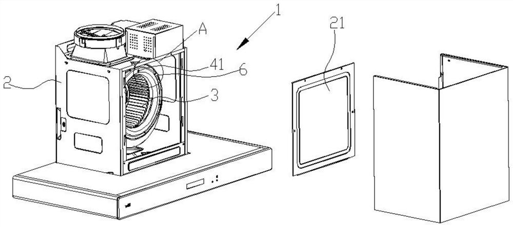
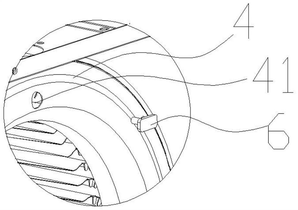
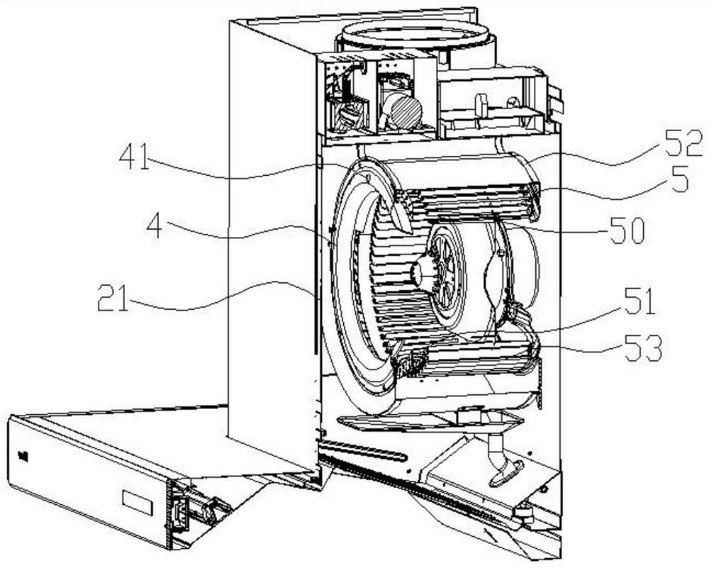
[0020] A cigarette machine 1, comprising a box body 2 and a fan system 3 arranged in the box body 2, the fan system 3 includes an air inlet ring 4 and an impeller device 5, and the air inlet ring 4 is arranged on the impeller At the air inlet of the device 5, the air inlet ring 4 is provided with a through hole 41, the impeller device 5 includes an impeller rim 50, and a distance measuring module 6 is arranged inside the box body 2, and the distance measuring module 6 Facing the through hole 41 to measure the distance between the ranging module 6 and the impeller rim 50 through the through hole 41 .


PUM


Abstract

The invention provides a range hood. The range hood comprises a box body and a fan system arranged in the box body, wherein the fan system comprises an air inlet ring and an impeller device, wherein the air inlet ring is arranged at an air inlet of the impeller device; a through hole is arranged in the air inlet ring; the impeller device comprises an impeller rim; a distance measuring module is arranged at the inner side of the box body; the distance measuring module faces the through hole; and the distance measuring module measures the distance between the distance measuring module and the impeller rim through the through hole. When the impeller device operates, the distance measuring module measures the distance between the distance measuring module and the impeller rim in real time in order to detect the variation of the axial displacement of the impeller device, and whether the impeller device operates abnormally or not is detected by judging whether the variation of the axial displacement of the impeller device exceeds a preset threshold value or not.

Description


Claims


Application Information

Patent Timeline
Owner VATTI CORP LTD
Why Eureka
Try Eureka