Workpiece surface treatment method based on image recognition and shot blasting machine

A technology of workpiece surface and processing method, applied in image data processing, used abrasive processing device, image analysis, etc., can solve the problems of wasting time and lack of machine detection, saving working time and improving the effect of shot blasting Effect

Pending Publication Date: 2021-07-20
YANCHENG INST OF TECH
View PDF6 Cites 1 Cited by
  • Summary
  • Abstract
  • Description
  • Claims
  • Application Information

AI Technical Summary

Problems solved by technology

The effect of workpiece processing lacks the process of machine detection. If there is in

Method used


Image

  • Workpiece surface treatment method based on image recognition and shot blasting machine
  • Workpiece surface treatment method based on image recognition and shot blasting machine
  • Workpiece surface treatment method based on image recognition and shot blasting machine

Examples


Embodiment Construction

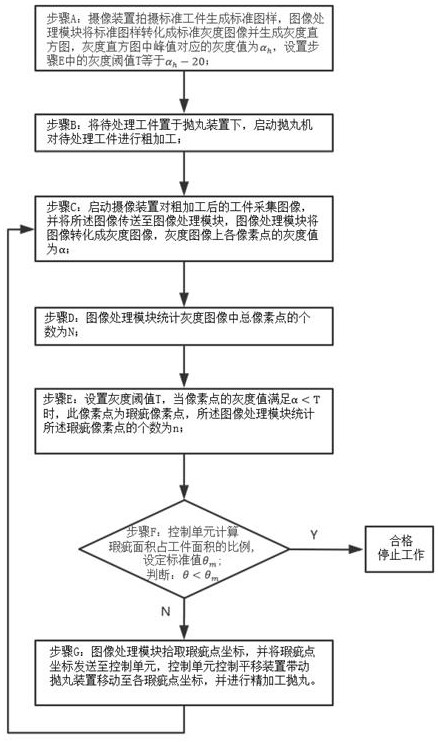
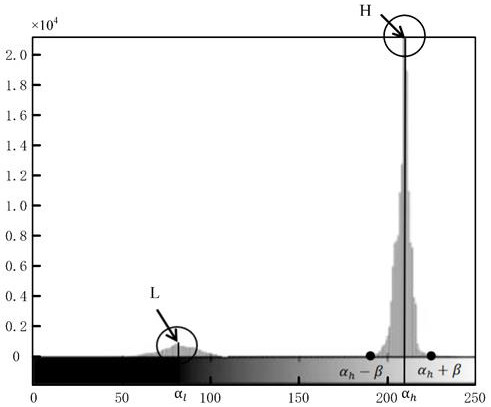
[0040] The invention discloses a workpiece surface treatment method based on image recognition. The method is applied to a shot blasting machine. Decide if secondary processing is required. The oxide skin can be the rust spots on the surface of the metal workpiece, etc. This method can significantly improve the processing effect and efficiency, and the present embodiment will be further described below in conjunction with the accompanying drawings:

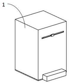
[0041] Such as figure 1 As shown, a workpiece surface treatment method based on image recognition, the method is applied to a shot blasting machine, the shot blasting machine includes a shot blasting device, a translation device, a camera device, an image processing module and a control unit;

[0042] The translation device drives the shot blasting device to move on the same horizontal plane;

[0043] The camera device is used to photograph the workpiece and transmit the captured image to the image processing module;

[0044] The


PUM


Abstract

The invention discloses a workpiece surface treatment method based on image recognition and a shot blasting machine, and relates to the field of shot blasting machines. The shot blasting machine comprises a shot blasting device, a translation device, a camera device, an image processing module and a control unit. After the shot blasting device machines a workpiece, the camera device shoots an image and transmits the shot image to the image processing module, the image processing module converts the image into a gray level image, identifies defective spots according to the gray level value of each pixel point on the gray level image and generates identification information, the identification information comprises the number of defective pixel points, the total number of the pixel points of the gray level image and coordinates of the defective pixel points, and the control unit judges whether machining is qualified or not according to the identification information and controls the shot blasting device and the translation device to conduct secondary machining on the unqualified workpiece. According to the method and the shot blasting machine, the shot blasting treatment effect can be effectively improved, the repeated loading process caused by unqualified workpieces is avoided, and the working time is saved.

Description


Claims


Application Information

Patent Timeline
Owner YANCHENG INST OF TECH
Why Eureka
Try Eureka