Device and method for laser direct imaging on uneven surface of workpiece

A technology of laser direct imaging and workpiece, which is applied in the direction of exposure device, optics, and optomechanical equipment of photoplate making process, and can solve the problems of inability to directly image with laser

Active Publication Date: 2021-08-31
深圳市先地图像科技有限公司
View PDF8 Cites 0 Cited by
  • Summary
  • Abstract
  • Description
  • Claims
  • Application Information

AI Technical Summary

Problems solved by technology

[0003] The present invention provides a device and imaging method for laser direct imaging on the uneven surface of the workpiece, and i

Method used


Image

  • Device and method for laser direct imaging on uneven surface of workpiece

Examples


Embodiment Construction

[0035] The following will clearly and completely describe the technical solutions in the embodiments of the present invention with reference to the accompanying drawings in the embodiments of the present invention. Obviously, the described embodiments are only some, not all, embodiments of the present invention. Based on the embodiments of the present invention, all other embodiments obtained by persons of ordinary skill in the art without making creative efforts belong to the protection scope of the present invention.

[0036] In the description of the present invention, it should be noted that the terms "center", "upper", "lower", "left", "right", "vertical", "horizontal", "inner", "outer" etc. The indicated orientation or positional relationship is based on the orientation or positional relationship shown in the drawings, and is only for the convenience of describing the present invention and simplifying the description, rather than indicating or implying that the referred devi


PUM


Abstract

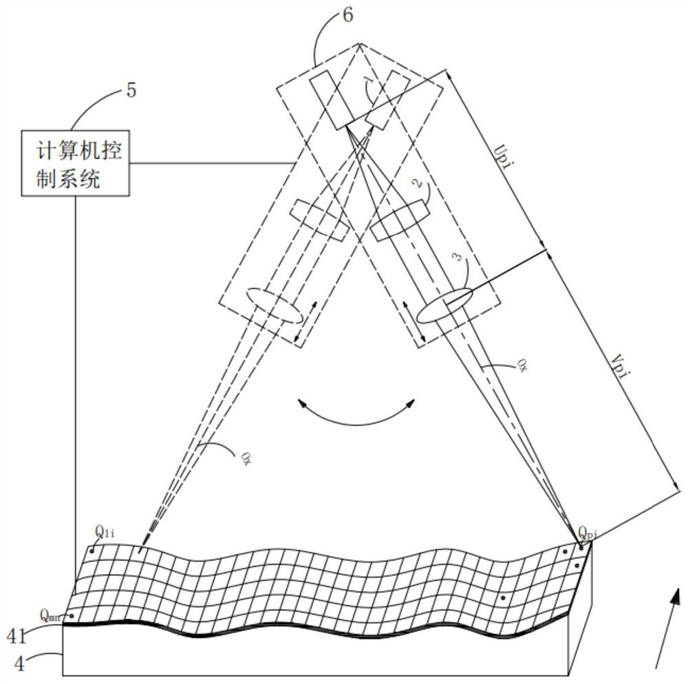
The invention discloses a device for laser direct imaging on an uneven surface of a workpiece. The device comprises a computer control system, and at least one group of light-emitting light source, collimating mirror and imaging lens which are integrally arranged on an optical axis, and the uneven surface of the workpiece is coated with a photosensitive ink layer. The light-emitting source, the collimating lens and the imaging lens are controlled by the computer control system to integrally swing back and forth to scan points to be exposed on the photosensitive ink layer. The computer control system is used for controlling the light-emitting light source, the collimating lens, the imaging lens and the workpiece to work cooperatively, so that emergent light is subjected to multiple times of reciprocating scanning on the photosensitive ink layer, and all the points to be exposed are exposed. The invention further discloses a method for direct laser imaging on the uneven surface. According to the device and the method, the problem that laser imaging cannot be directly carried out on an uneven surface is solved.

Description


Claims


Application Information

Patent Timeline
Owner 深圳市先地图像科技有限公司
Why Eureka
Try Eureka