Walking power assisting device

A technology of a power assist device and a support plate, which is used in appliances to help people walk, physical therapy, etc., can solve problems such as failure, neglect of foot movement, and increase in ankle joint exercise load.

Inactive Publication Date: 2021-11-16
SUN YAT SEN UNIV
View PDF12 Cites 0 Cited by
  • Summary
  • Abstract
  • Description
  • Claims
  • Application Information

AI Technical Summary

Benefits of technology

The inventor's walker helps people with arthritis or other issues better move around their feet without getting tired easily due to weight bearing over time. It uses special parts like leg cuffs made up of rubber material instead of traditional shoes for stability during movement. When wearing this shoe, our legs are supported at different points along its length depending upon how well it supports them when they stand still (the angle between these two points). This design allows us to lift heavy objects more efficiently than current designs because there will be less force needed to keep everything stable even if some things get stuck) resulting in fewer problems associated with muscle fatigue caused by prolonged sitting posture.

Problems solved by technology

This patented technology helps individuals walk better without having their feet constantly moving around or being tired after they have been stationary for too long time. However, current devices only help them move forward while sitting down instead of doing anything else effectively. They also increase muscle stress at the anus bone caused by weight bearing overall.

Method used


Image

  • Walking power assisting device
  • Walking power assisting device
  • Walking power assisting device

Examples


Embodiment Construction

[0023] The following will clearly and completely describe the technical solutions in the embodiments of the present invention with reference to the accompanying drawings in the embodiments of the present invention. Obviously, the described embodiments are only some, not all, embodiments of the present invention. Based on the embodiments of the present invention, all other embodiments obtained by persons of ordinary skill in the art without creative efforts fall within the protection scope of the present invention.

[0024] In the description of the present invention, it should be noted that the terms "center", "longitudinal", "transverse", "upper", "lower", "front", "rear", "left", "right", " The orientations or positional relationships indicated by "vertical", "horizontal", "top", "bottom", "inner" and "outer" are based on the orientations or positional relationships shown in the drawings, and are only for the convenience of describing the present invention and Simplified descri


PUM


Abstract

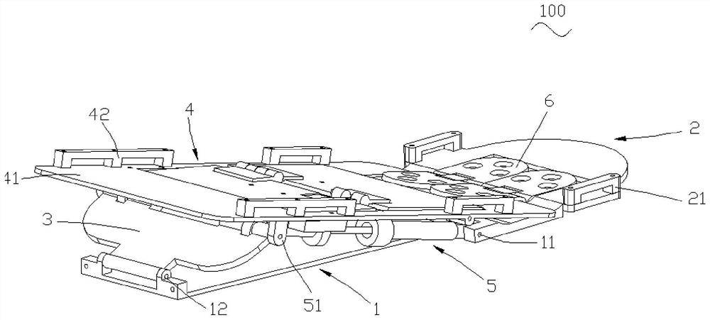
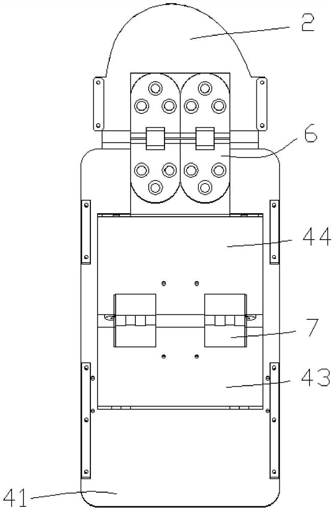
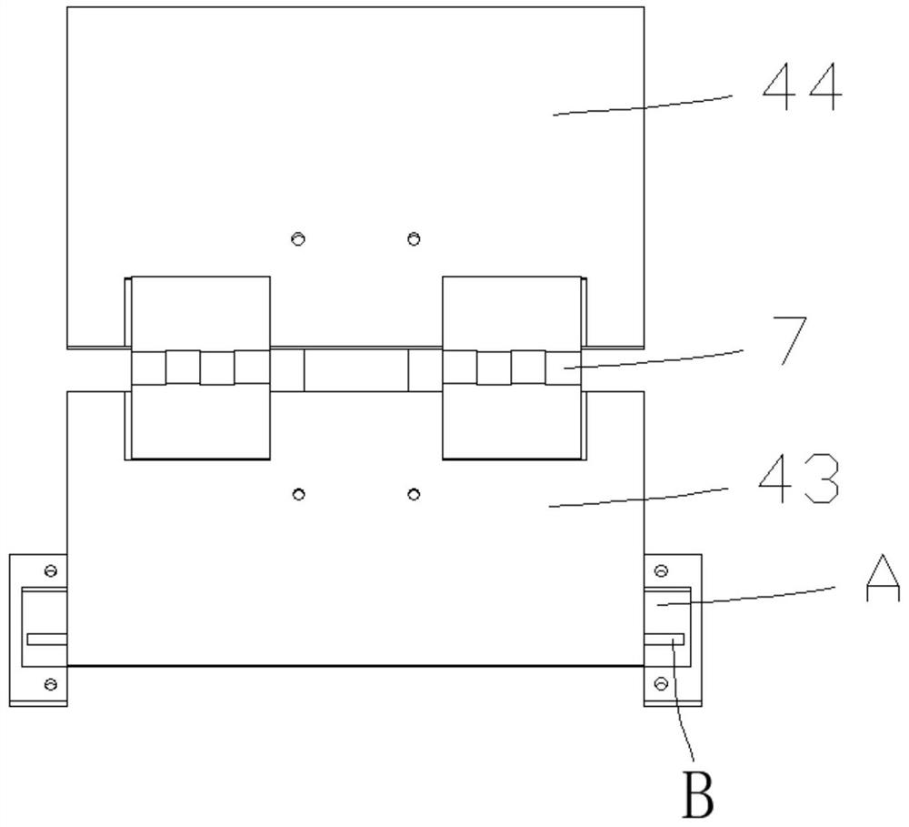
The invention relates to the technical field of walking assisting instruments, in particular to a walking assisting device which comprises a bottom plate, a toe plate, a pressing plate, a supporting plate and a first elastic assembly, wherein the toe plate is hinged to the supporting plate, the toe plate and the bottom plate are hinged to one end of the first elastic assembly, the bottom plate is hinged to the pressing plate, and the pressing plate and the supporting plate are hinged to the other end of the first elastic assembly. The first supporting plate is obliquely connected to the bottom plate, and a first fixing part fixedly connected with toes is arranged on the upper surface of the toe plate. During use, toes are fixedly connected with the toe plate through the first fixing part, when a human body is in a standing state, gravity acts on the supporting plate to enable the supporting plate to rotate to be attached to the bottom plate, meanwhile, the supporting plate acts on the pressing plate and the first elastic assembly to enable the pressing plate to rotate, and the first elastic assembly is extruded to convert gravitational potential energy into elastic potential energy; then, in the state of lifting the foot, the gravity is concentrated on the toes to press the toe plate, and the elastic potential energy of the first elastic component is released to help the human body to lift the sole so as to realize the assistance of the foot.

Description


Claims


Application Information

Patent Timeline
Owner SUN YAT SEN UNIV
Why Eureka
Try Eureka