Alternating-current and direct-current integrated power distribution station

A technology for AC power distribution and DC power distribution, applied in the field of power distribution station construction, can solve problems such as the inability to meet the needs of DC load and DC facility access, achieve rich functions and functions, achieve integrated scheduling and control, and balance loads Effect

Pending Publication Date: 2022-02-01
SHANGHAI ELECTRIC POWER DESIGN INST
View PDF0 Cites 0 Cited by
  • Summary
  • Abstract
  • Description
  • Claims
  • Application Information

AI Technical Summary

Problems solved by technology

Therefore, the current single AC power distribution substation can

Method used


Image

  • Alternating-current and direct-current integrated power distribution station

Examples


Embodiment

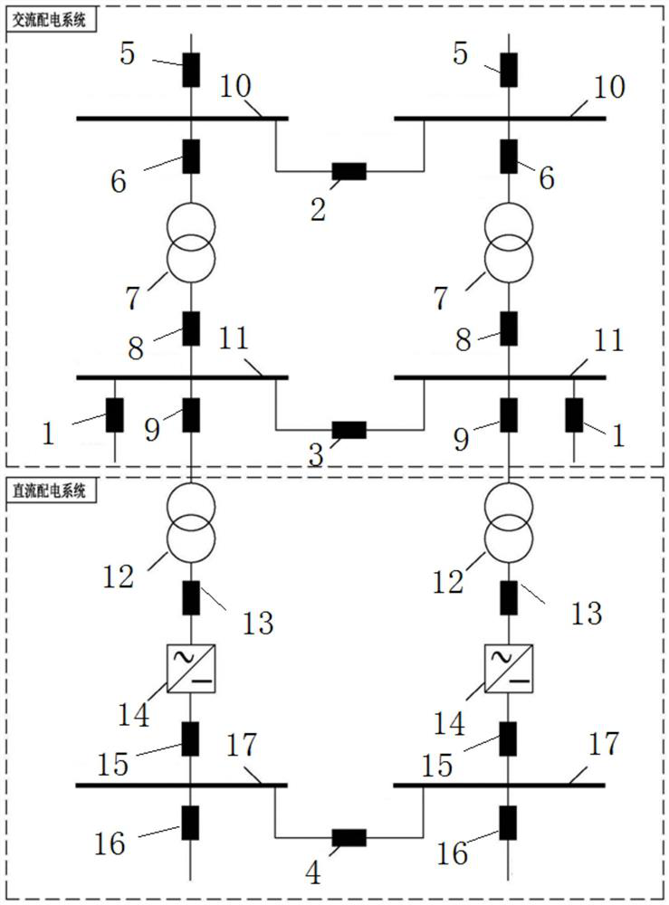
[0032] Such as figure 1 As shown, the AC-DC integrated distribution station includes the AC power distribution system and the DC power distribution system set in the distribution station room.

[0033] Among them, the AC power distribution system supplies power to the DC power distribution system through the 0.4kV feeder switch cabinet 1;

[0034] The AC power distribution system includes two sets of AC power distribution devices connected through 10kV section switch 2 and 0.4kV section switch 3;

[0035] The DC power distribution system includes two sets of DC power distribution devices connected through the 750V section switch 4;

[0036] Each AC power distribution device includes 10kV incoming switchgear 5, 10kV feeder switchgear 6, 10 / 0.4kV distribution transformer 7, 0.4kV receiving main switchgear 8, 0.4kV isolation transformer switchgear 9 and 0.4kV feeder switch cabinet 1;

[0037] A 10kV AC busbar 10 is provided between the 10kV incoming line switchgear 5 and the co


PUM


Abstract

The invention discloses an alternating-current and direct-current integrated power distribution station. The alternating-current and direct-current integrated power distribution station comprises an alternating-current power distribution system and a direct-current power distribution system which are arranged in a power distribution station room. The alternating-current power distribution system supplies power to the direct-current power distribution system through a 0.4 kV feeder switch cabinet; the alternating-current power distribution system comprises two sets of alternating-current power distribution devices which are connected in parallel through a 10kV section switch and a 0.4 kV section switch; and the direct-current power distribution system comprises two sets of direct-current power distribution devices which are connected through a 750V section switch. According to the alternating-current and direct-current integrated power distribution station of the invention, on the basis of satisfying a conventional alternating-current power distribution function, the access requirement of a direct-current power supply and a load can be met.

Description


Claims


Application Information

Patent Timeline
Owner SHANGHAI ELECTRIC POWER DESIGN INST
Why Eureka
Try Eureka