Helical bevel gear meshing system vibration characteristic analysis method and system
A technology of bevel gears and vibration characteristics, applied in special data processing applications, instruments, electrical digital data processing, etc., can solve the problems of inability to reflect, rough calculation, and inability to reflect the influence of the critical speed of gear system parameters, etc., and achieve accurate and stable results , the effect of fast calculation speed
- Summary
- Abstract
- Description
- Claims
- Application Information
AI Technical Summary
Problems solved by technology
Method used
Image

Examples
Example Embodiment
[0056] Example 1
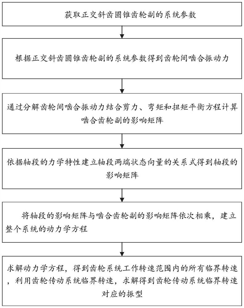
[0057] like figure 1 As shown, this embodiment discloses a vibration characteristic analysis method of a helical bevel gear meshing system, including the following steps:
[0058] Step 1: Obtain the system parameters of the orthogonal helical bevel gear pair;
[0059] The gear system parameters include: gear mass, moment of inertia, polar moment, pitch radius, gear tooth stiffness, pressure angle, helix angle, taper angle, shaft length, shaft diameter, shaft section moment of inertia, Young's elastic modulus quantity, bearing stiffness.
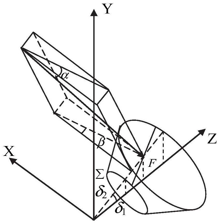
[0060] The parameters include the generalized force and displacement vector of the orthogonal helical bevel gear pair, the generalized force includes shear force, bending moment, and torque, and the displacement includes relative displacement of the shaft center, deflection angle, torsion angle, and the like.
[0061] In this embodiment, the positive direction of shear force and bending moment is different from the provisio
Example Embodiment
[0130] Embodiment 2
[0131] This embodiment provides a vibration characteristic analysis system of a helical bevel gear meshing system, including:
[0132] A system parameter acquisition module, which is configured to acquire system parameters of the orthogonal helical bevel gear pair;
[0133] a vibration force calculation module, which is configured to: obtain the meshing vibration force between the gears according to the system parameters of the orthogonal helical bevel gear pair;
[0134] a vibration force decomposition module, which is configured to: calculate the influence matrix of the meshing gear pair by decomposing the meshing vibration force between the gears in combination with the shear force, bending moment and torque balance equation;
[0135] According to the mechanical characteristics of the shaft segment, the influence matrix of the shaft segment is obtained by establishing the relational expressions of the state parameters at both ends of the shaft segment;
Example Embodiment
[0138] Embodiment 3
[0139] Embodiments of this specification provide a computer device, including a memory, a processor, and a computer program stored in the memory and running on the processor, where the processor implements the helical gear in Embodiment 1 when the processor executes the program Steps of a method for analyzing vibration characteristics of bevel gear meshing systems.
PUM
 Abstract
Description
Claims
Application Information
 - R&D Engineer
- R&D Manager
- IP Professional
- Industry Leading Data Capabilities
- Powerful AI technology
- Patent DNA Extraction
Browse by: Latest US Patents, China's latest patents, Technical Efficacy Thesaurus, Application Domain, Technology Topic.
© 2024 PatSnap. All rights reserved.Legal|Privacy policy|Modern Slavery Act Transparency Statement|Sitemap