Electromagnetic bearing control method, device and system

An electromagnetic bearing and bearing technology, which is applied in mechanical bearing testing, instruments, character and pattern recognition, etc., can solve problems such as rotor and bearing damage, unit shutdown, rotor and bearing friction, etc., to improve stability, improve control performance, Improve the effect of the control effect

Active Publication Date: 2022-07-08
GREE ELECTRIC APPLIANCES INC
View PDF4 Cites 0 Cited by
  • Summary
  • Abstract
  • Description
  • Claims
  • Application Information

AI Technical Summary

Problems solved by technology

[0003] In view of this, the embodiment of the present invention provides an electromagnetic bearing control method, device and system to overcome the existing electromagnetic bearings in the

Method used


Image

  • Electromagnetic bearing control method, device and system
  • Electromagnetic bearing control method, device and system
  • Electromagnetic bearing control method, device and system

Examples


Embodiment Construction

[0051] In order to make the purposes, technical solutions and advantages of the embodiments of the present invention clearer, the technical solutions in the embodiments of the present invention will be clearly and completely described below with reference to the accompanying drawings in the embodiments of the present invention. Obviously, the described embodiments These are some embodiments of the present invention, but not all embodiments. Based on the embodiments of the present invention, all other embodiments obtained by those skilled in the art without creative efforts shall fall within the protection scope of the present invention.

[0052] In the description of the present invention, it should be noted that the terms "center", "upper", "lower", "left", "right", "vertical", "horizontal", "inner", "outer", etc. The indicated orientation or positional relationship is based on the orientation or positional relationship shown in the accompanying drawings, which is only for the c


PUM


Abstract

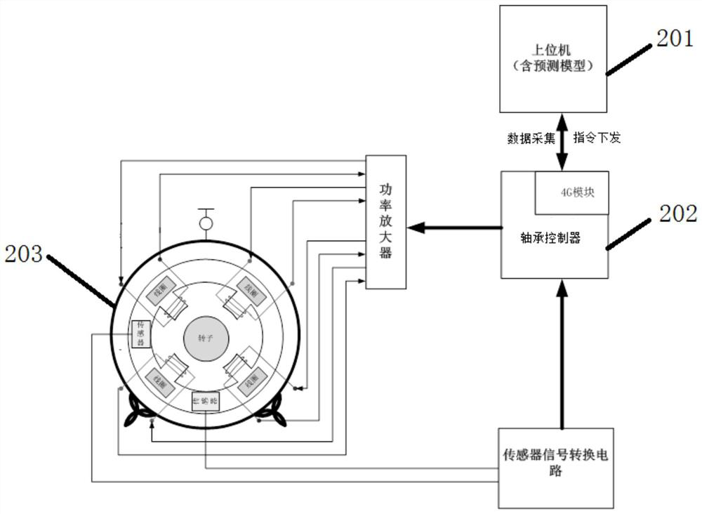
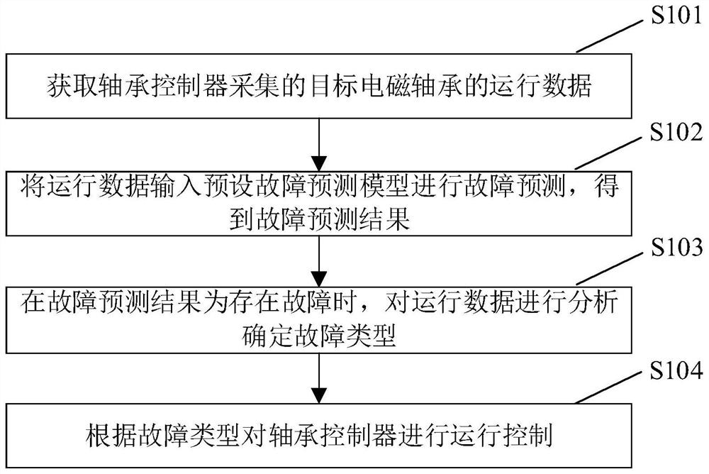
The invention provides an electromagnetic bearing control method, device and system. The method comprises the steps of obtaining operation data, collected by a bearing controller, of a target electromagnetic bearing; inputting the operation data into a preset fault prediction model for fault prediction to obtain a fault prediction result; when the fault prediction result is that a fault exists, analyzing the operation data to determine a fault type; and performing operation control on the bearing controller according to the fault type. Therefore, possible faults are predicted by collecting the operation data of the electromagnetic bearing through the bearing controller, when it is predicted that the bearing faults will occur, the fault type is determined according to the operation data, then operation control is conducted on the bearing controller, and the bearing operation fault rate and the rotor damage rate are reduced by conducting control intervention in advance; the bearing control performance is improved, the control effect is improved, and the stability of the whole system is improved.

Description


Claims


Application Information

Patent Timeline
Owner GREE ELECTRIC APPLIANCES INC
Why Eureka
Try Eureka