Lens shifter

A lens movement and lens technology, applied in the directions of driving/moving recording heads, head configuration/installation, instruments, etc., can solve problems such as difficulty in responding to driving forces, increasing the weight of moving parts, and high cost of components and assembly

Inactive Publication Date: 2004-11-24
SONY CORP
View PDF0 Cites 0 Cited by
  • Summary
  • Abstract
  • Description
  • Claims
  • Application Information

AI Technical Summary

Problems solved by technology

[0022] Therefore, more components must be utilized, which results in high cost of components and assembly
In addition, the balance weight 8 added to the movable section assembly increases the wei

Method used


Image

  • Lens shifter
  • Lens shifter
  • Lens shifter

Examples


Embodiment Construction

[0037]Reference will be made to the embodiments of the present invention below Figure 1 ~ Figure 4 Give a detailed description.

[0038] It is worth noting that although various better technical indicators have been described, and what is described below is a more optimized embodiment of the invention, the scope of the present invention is not limited to this form unless there is a reference to the present invention in the following descriptions. Invention specific limitations.

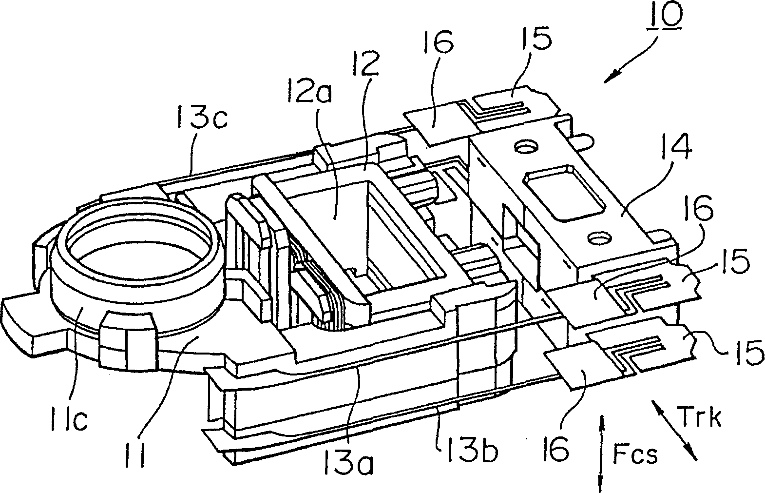
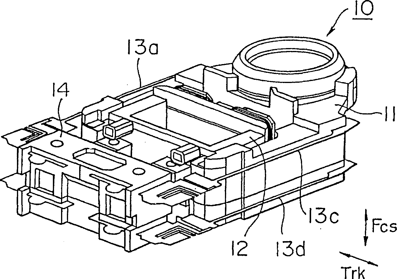
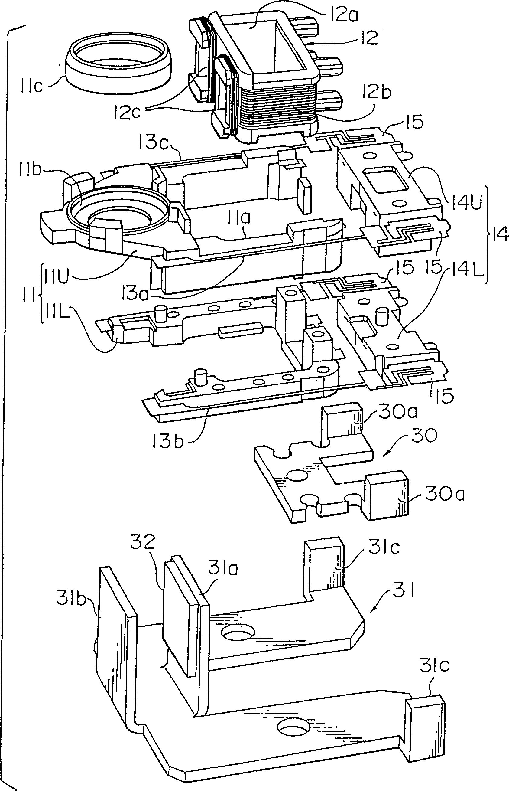
[0039] Figure 1 to Figure 3 Shown is a biaxial actuator of an embodiment of the invention. for Figure 1 to Figure 3 , a biaxial actuator includes a lens holder 11, a coil bobbin 12, a set of elastic supports 13a, 13b, 13c, 13d, a fixed portion 14 and a deflection coil 31.

[0040] Such as image 3 As shown, the aforementioned lens holder 11 is divided into an upper half 11U and a lower half 11L by a horizontal dividing line, and the two parts are connected together. Lens holder 11, such as ima


PUM


Abstract

A lens moving apparatus of the present invention is used in an optical pickup of, for example, an optical recording/reproducing system. The apparatus includes a moving assembly holding an objective lens and provided with a coil bobbin, elastic supporting devices which support the moving assembly along the focusing dimension and the tracking dimension, focusing coils and tracking coils wound on the coil bobbin, and a magnetic circuit formed by a yoke and a magnet. The center of gravity of the moving assembly is positioned so that the product of the distance from an effective section of the focusing coil to the center of gravity of the moving assembly and the force produced at the effective section is about equal to the product of the distance from a noneffective section of the focusing coil to the center of gravity of the moving assembly and the force produced at the noneffective section.

Description


Claims


Application Information

Patent Timeline
Owner SONY CORP
Why Eureka
Try Eureka