Handle structure of vacuum cleaner
A vacuum cleaner and handle technology, which is applied to the handle and other directions, can solve the problems of complicated installation process of the handle, difficult disassembly and disassembly of the handle, etc., and achieves the effects of simple production and maintenance, convenient separation and installation, and reduced manufacturing costs.
- Summary
- Abstract
- Description
- Claims
- Application Information
AI Technical Summary
Problems solved by technology
Method used
Image

Examples
Embodiment Construction
[0027] Next, specific embodiments of the present invention will be described in detail with reference to the accompanying drawings.
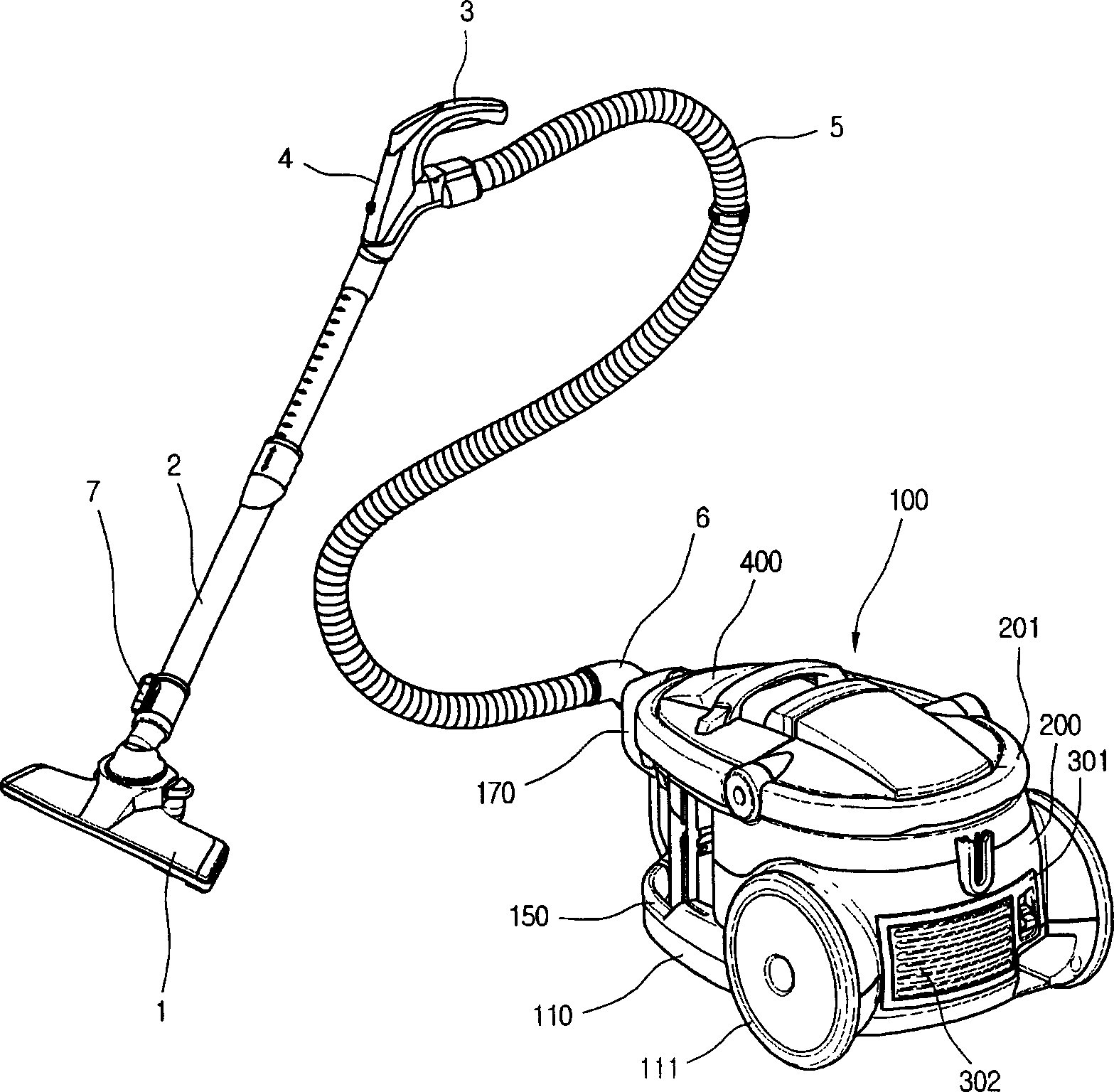
[0028] figure 1 It is a perspective view of the vacuum cleaner of this invention.
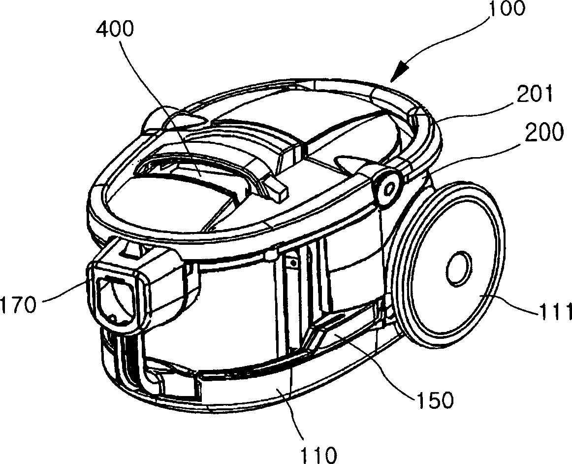
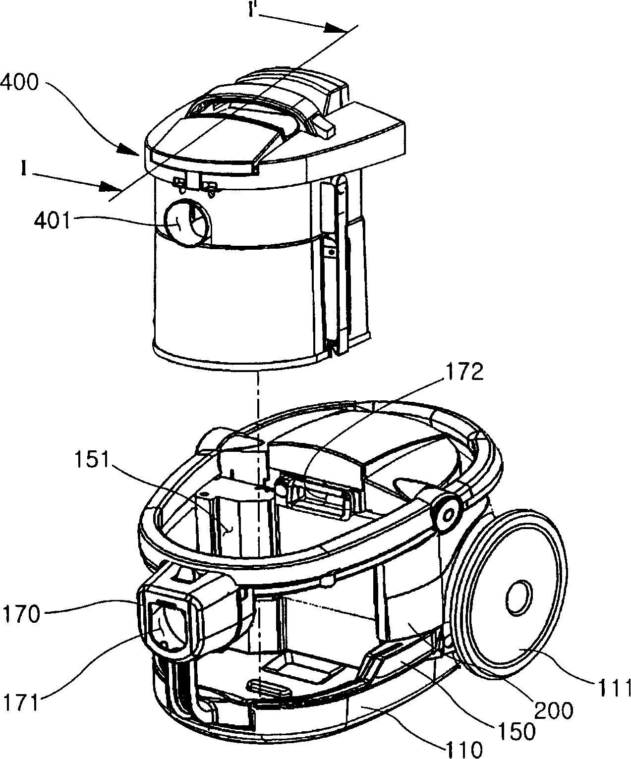
[0029] Such as figure 1 As shown, the vacuum cleaner of the present invention includes: a vacuum cleaner body 100 and a suction pipe connected to the suction side of the vacuum cleaner body 100 . At least an air suction fan and a dust collection unit are arranged inside the vacuum cleaner body 100 , and after filtering out foreign objects in the sucked air, clean air is sent outside.
[0030] The suction pipe is a duct for sucking air containing foreign matter using suction inside the vacuum cleaner body 100 . Specifically, the suction pipe includes: a suction nozzle 1 that uses a strong air flow to suck air containing foreign matter from the outside; The operating handle 3 at the end of the tube 2; the operating end 4 which is arranged in front of the operating
PUM
 Abstract
Description
Claims
Application Information
 - R&D Engineer
- R&D Manager
- IP Professional
- Industry Leading Data Capabilities
- Powerful AI technology
- Patent DNA Extraction
Browse by: Latest US Patents, China's latest patents, Technical Efficacy Thesaurus, Application Domain, Technology Topic.
© 2024 PatSnap. All rights reserved.Legal|Privacy policy|Modern Slavery Act Transparency Statement|Sitemap