Stackable system container

a system container and container body technology, applied in the direction of containers, rigid containers, packaging, etc., can solve the problem of less modularity of the system container system

Active Publication Date: 2020-12-22
BS SYST GMBH &CO KG
View PDF32 Cites 5 Cited by
  • Summary
  • Abstract
  • Description
  • Claims
  • Application Information

AI Technical Summary

Benefits of technology

This patented technology allows two coupled systems (coupling devices) to secure their positions during transportation without requiring tools like bolts. It achieves these technical results because it includes features where certain components are secured together when they're used inside containers made from plastic material. These improvements make sure no accidental openings occur while still being able to maintain good sealing between them.

Problems solved by technology

In this patented technology there is described a type of packaging called a Stackable System Container (SSC). It consists of three parts: its base or main body made of plastic material like polyethylene terephthalate; it's covered with a layer of foil paper to protect them during shipping and handling. There may have multiple systems attached inside it, including smaller ones stored separately within larger units. These small packages allow users easy access while still being able to store many types of items together without taking extra effort.

Method used


Image

  • Stackable system container
  • Stackable system container
  • Stackable system container

Examples


Embodiment Construction

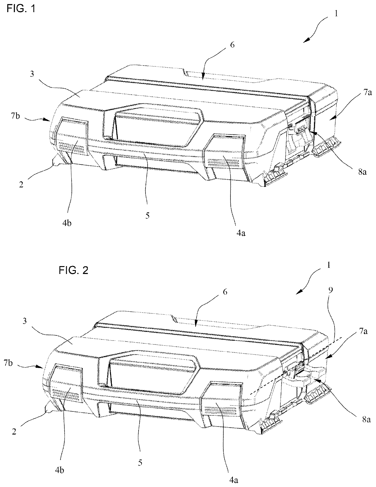
[0032]A perspective view of a stackable system container 1 is shown in FIG. 1. The system container 1 includes a lower bottom part 2 and an upper lid 3 fastened to pivot on the bottom part 2. The lid 3, however, could also be designed separately from the bottom part 2. The bottom part 2 has an upward-facing storage space (not shown), which is bounded on top by the lid 3. The lid 3 is connected to pivot with the bottom part 2 via a swivel joint arranged on the rear edge of the lid 3. In order to fasten the lid 3 releasably to the bottom part 2 and thus reliably close the enclosed storage space, two closure devices 4a, 4b are provided on the front side of the system container 1 that are articulated on the lid 3 and cooperate in locking fashion with the bottom part 2 in the depicted closed position of the lid 3.

[0033]The system container 1 can be used, for example, for transport and storage of tools and working materials for craftsmen. For this purpose, the bottom part 2 preferably has a


PUM


Abstract

A stackable system container includes a bottom part and a lid part fastened to the bottom part. Respective coupling devices are movably fastened to two opposite side walls of the bottom part. In order to enable dimensionally stable and connected stacking of structurally identical system containers and also modular stacking of different system containers, each coupling device can be moved between an idle position, in which the coupling device is arranged below a top side of the lid part, and a coupling position, in which the coupling device projects beyond the top side of the lid part.

Description


Claims


Application Information

Patent Timeline
Owner BS SYST GMBH &CO KG
Why Eureka
Try Eureka