Variable stiffness mechanism and limb support device incorporating the same

a variable stiffness and limb technology, applied in the field of variable stiffness mechanisms, can solve the problems of low energy return, limited stability of high energy return feet, and inability to achieve energy efficient gait patterns, etc., and achieve the effect of high apparent viscosity

Active Publication Date: 2021-04-20
OSSUR ICELAND EHF
View PDF197 Cites 1 Cited by
  • Summary
  • Abstract
  • Description
  • Claims
  • Application Information

AI Technical Summary

Benefits of technology

This patent describes a device that uses a rod with two parts - one part attached to it and another part attached to the other. A sealing opening in each part allows the rod to move freely while keeping the inside filled with liquid. There are also three flexible members: a pump, an accumulator, and a pyramid connector. These components help control the flow of fluid during movement.

Problems solved by technology

The technical problem addressed in this patent text relates to improving the functioning and reliability of prosthetic feet that work well on different types of terrain (lowered surfaces) without requiring excessive power from their own motors.

Method used


Image

  • Variable stiffness mechanism and limb support device incorporating the same
  • Variable stiffness mechanism and limb support device incorporating the same
  • Variable stiffness mechanism and limb support device incorporating the same

Examples


Embodiment Construction

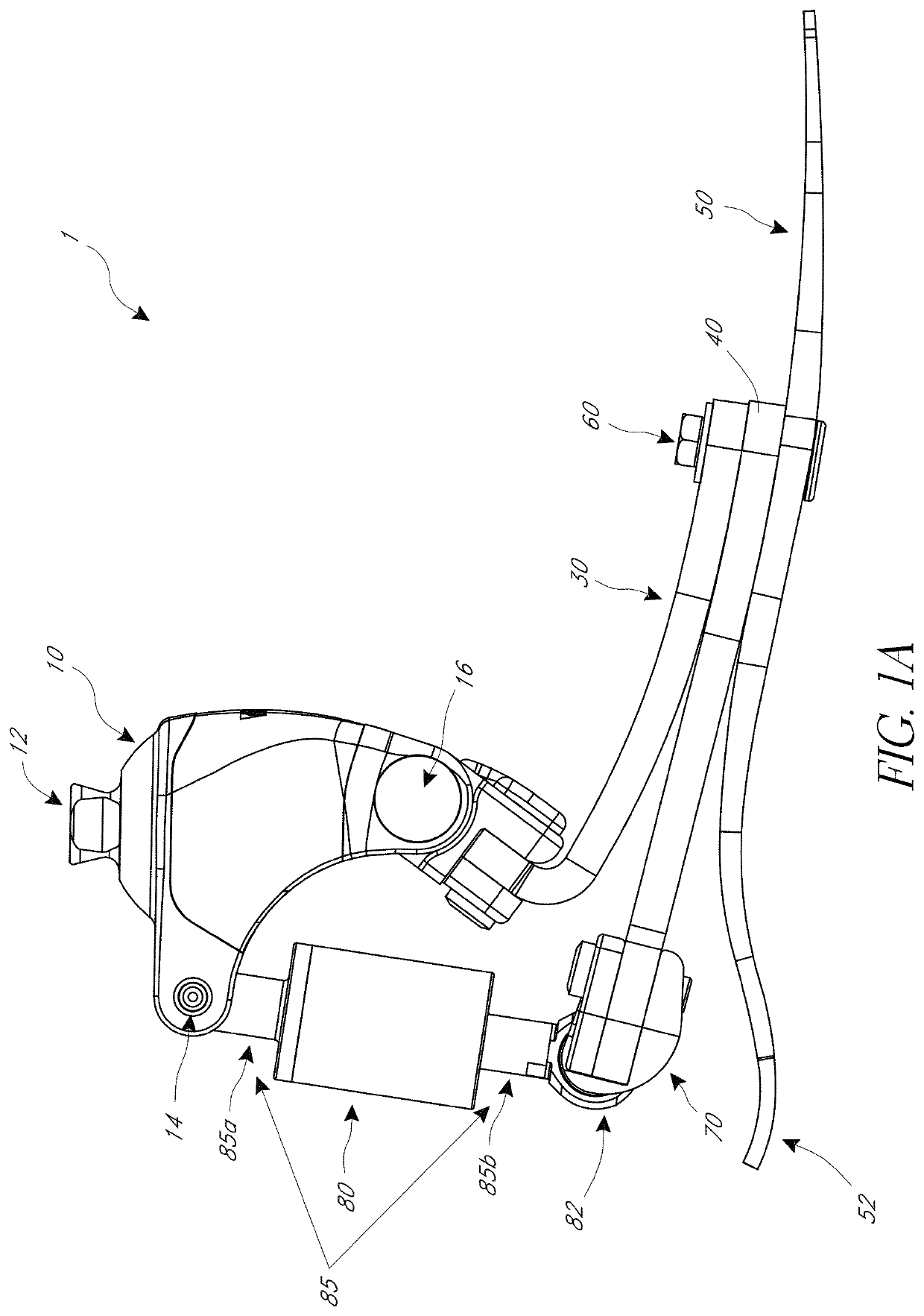
[0038]A natural human ankle varies its stiffness based on the activity being performed by the user, such as walking at various speeds, rising to stand from a seated position, sitting down, ascending and descending stairs, walking on uneven terrain, and / or running. The ankle can vary between, for example, relatively low stiffness and relatively high damping during slow walking, which can allow for easier transitions, and relatively higher stiffness and relatively lower damping when walking at faster speeds, which can provide greater energy efficiency. Some currently available prosthetic feet are adapted for either high damping, e.g., via a hydraulic mechanism, or high energy efficiency, e.g., via carbon fiber leaf springs. However, such prosthetic feet typically have fixed damping and / or spring characteristics optimized for a particular gait speed on level ground and may not adapt well to other speeds or activities. While prosthetic feet including an electric motor in series with a


PUM


Abstract

A limb support device includes a variable stiffness mechanism. The limb support device can be an orthotic or prosthetic device. The variable stiffness mechanism can include, for example, a rate-sensitive or speed-dependent material or a damping mechanism. The variable stiffness mechanism causes the limb support device to exhibit different properties when the user of the limb support device is walking at high or fast walking speeds compared to low or slow walking speeds. The limb support device can exhibit high damping and energy absorption, and therefore stability, at slow speeds, and high energy return at faster speeds.

Description


Claims


Application Information

Patent Timeline
Owner OSSUR ICELAND EHF
Why Eureka
Try Eureka