Cut-in box

Inactive Publication Date: 2003-05-08
HODZIC AVDO
View PDF0 Cites 4 Cited by
  • Summary
  • Abstract
  • Description
  • Claims
  • Application Information

AI Technical Summary

Problems solved by technology

The conventional cut-in boxes and installation parts create some very significant practical problems.
One problem is that the installation of a conventional cut-in box commonly requires the installer to bring out the cable(s) from behind the wall opening and route the cable(s) through a hole in one sidewall of the cut-in box enclosure, then push the cut-in box through the wall opening.
However, since the cable(s) are now routed through the hole in the enclosure of the cut-in box, the rectangular shaped cut-in box cannot simply be pushed straight through the wall opening.
Another problem is that the installer frequently has to weaken the wall by making a notch cut in the perimeter of the wall opening when the cable(s) (e.g., metal cables, armored cables, non-metallic cables, and other equivalents) are pulled out through the wall opening for the initial cable routing and connection.
The installer then installs and attaches labor-intensive mounting brackets to hold the cut-in box firmly against the perimeter of the wall around the wall opening.
An even worse problem than a notch cut in the wallboard around the wall opening is that some cable(s) cannot even normally be pulled out from behind the wallboard for connection to a conventional cut-in box, particularly if the cable(s) are enclosed in a large diameter metal conduit or flexible metal conduit when it is required by building codes, or if the wall is thicker than normal (e.g., it is a firewall or a wall constructed from a thick wallboard).
Then the installer must retrieve the guide wire from the flexible metal conduit, which can be difficult.
Therefore, the installation of a conventional cut-in box involves a large investment in labor time and labor cost, significantly limiting the number of conventional cut-in boxes that can be installed in a workday.
Another problem with the installation of a conventional cut-in box is the use of conventional mounting brackets (e.g., strips of thin sheet metal stamped in an "F" shape with the two parallel arms of the "F" designed to fold around the edges of the conventional cut-in box while clamping it against the wall).
These conventional mounting brackets are also typically designed to have the very thin sheet metal edge push into the wall perimeter around the wall opening, frequently pushing too deep into the wallboard during or after installation, producing a wobbling m

Method used


Image

  • Cut-in box
  • Cut-in box
  • Cut-in box

Examples


Embodiment Construction

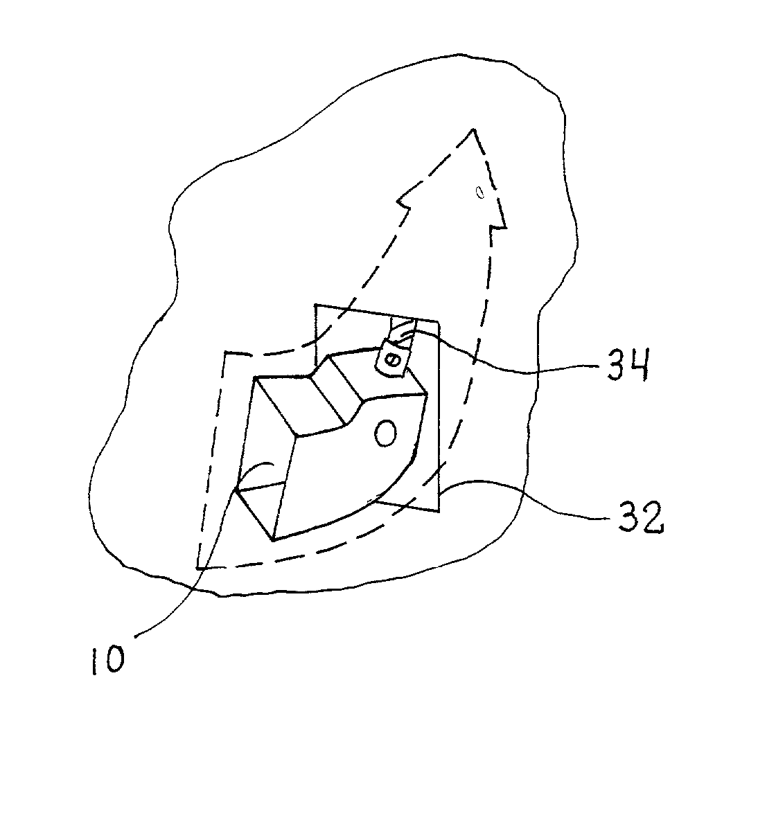
[0051] The present invention provides an improved cut-in box, an improved mounting bracket that can be used with an improved cut-in box or several other types of cut-in boxes, and an anti-short mechanism to minimize electrical shorts between a metal cut-in box and one or more electrical cables. The present invention can also be applied to a cut-in box for one or more optical fiber cables to be optically routed through a wall opening. While the discussion below is directed to an application of the invention to secure one cut-in box to a wall opening, the invention can also be applied to a "gang" or "bank" of cut-in boxes mounted in adjacent proximity in a wall opening. The invention can also be applied to cut-in boxes installed in the walls of large containers or vehicles (e.g., automobiles, airplanes, ships, trains, and so forth), as well as cut-in boxes installed in the walls of buildings.

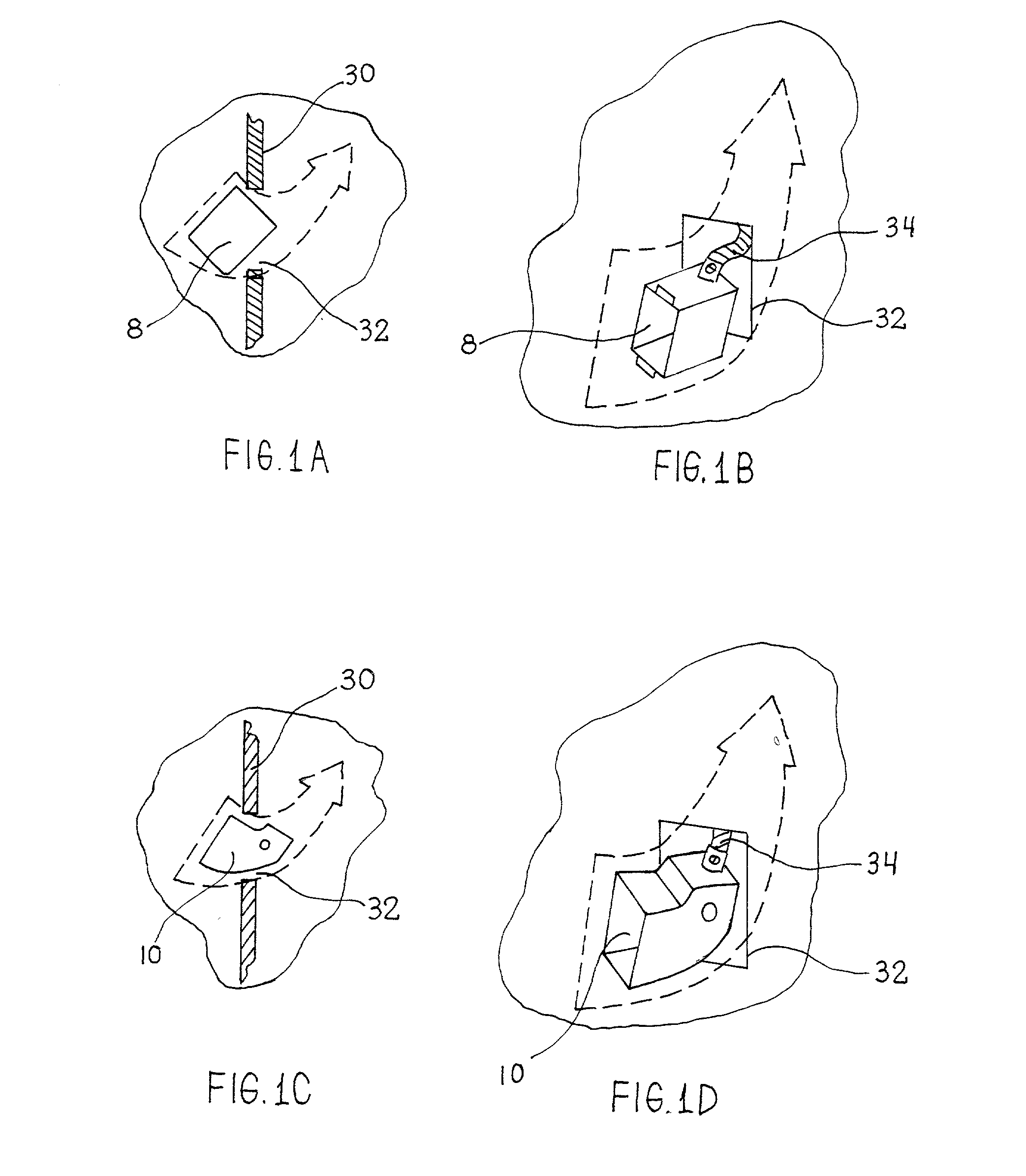
[0052] FIG. 1A illustrates a side view of a conventional cut-in box 8 being inserted through an o


PUM


Abstract

An improved cut-in box and parts to facilitate the installation of a cut-in box and the safer connection of a cut-in box to at least one cable behind a wall. The improved cut-in box does not require the time-consuming use of a guide wire to route a flexible conduit behind a wallboard through a hole in the cut-in box during the installation process. A first embodiment of the invention involves an improved cut-in box to facilitate connection to at least one cable behind a wall. A second embodiment of the invention involves a cut-in box mounting bracket to clamp a cut-in box to a wall opening. A third embodiment of the invention involves an anti-short mechanism for an electrical cut-in box.

Description


Claims


Application Information

Patent Timeline
Owner HODZIC AVDO
Why Eureka
Try Eureka