Staple detecting mechanism of electric stapler

Inactive Publication Date: 2004-12-09
MAX CO LTD
View PDF5 Cites 15 Cited by
  • Summary
  • Abstract
  • Description
  • Claims
  • Application Information

AI Technical Summary

Problems solved by technology

Therefore, the other end of the staple sensor 13 does not move over a distance sufficient enough to switch a signal for a not shown photointerruptor opposed to the sensor with the result that an erroneous signal may be generated.
Consequently, there are problems that not only the detection accuracy but also the durability of the staple sensor 13 itself drop.

Method used


Image

  • Staple detecting mechanism of electric stapler
  • Staple detecting mechanism of electric stapler
  • Staple detecting mechanism of electric stapler

Examples


Example

[0036] In the following, one embodiment of the staple sheet-detecting mechanism of the electric stapler according to the present invention will be explained with reference to the drawings.

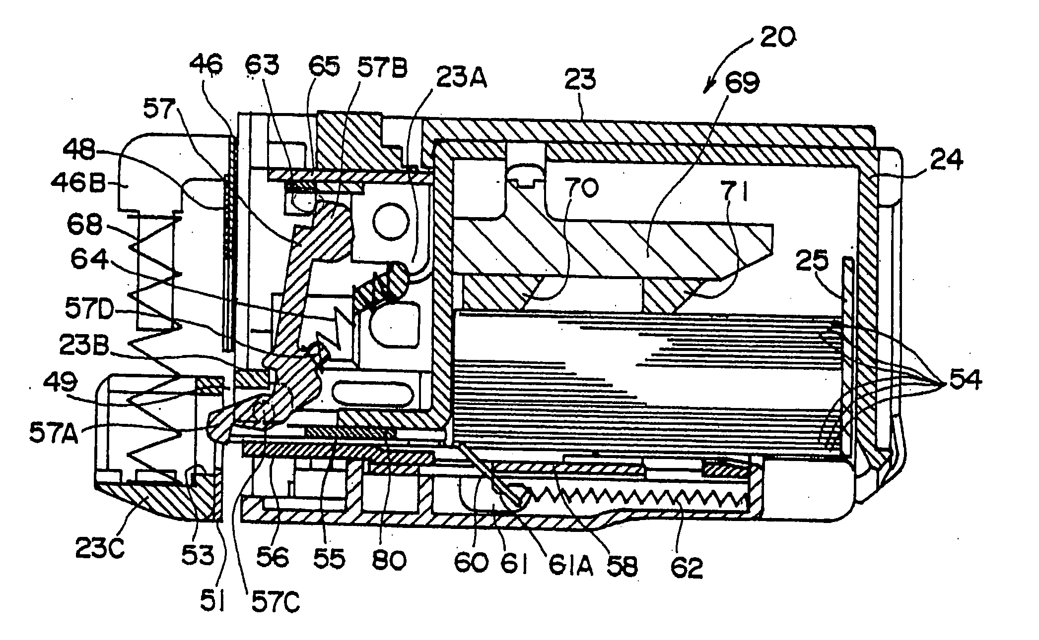
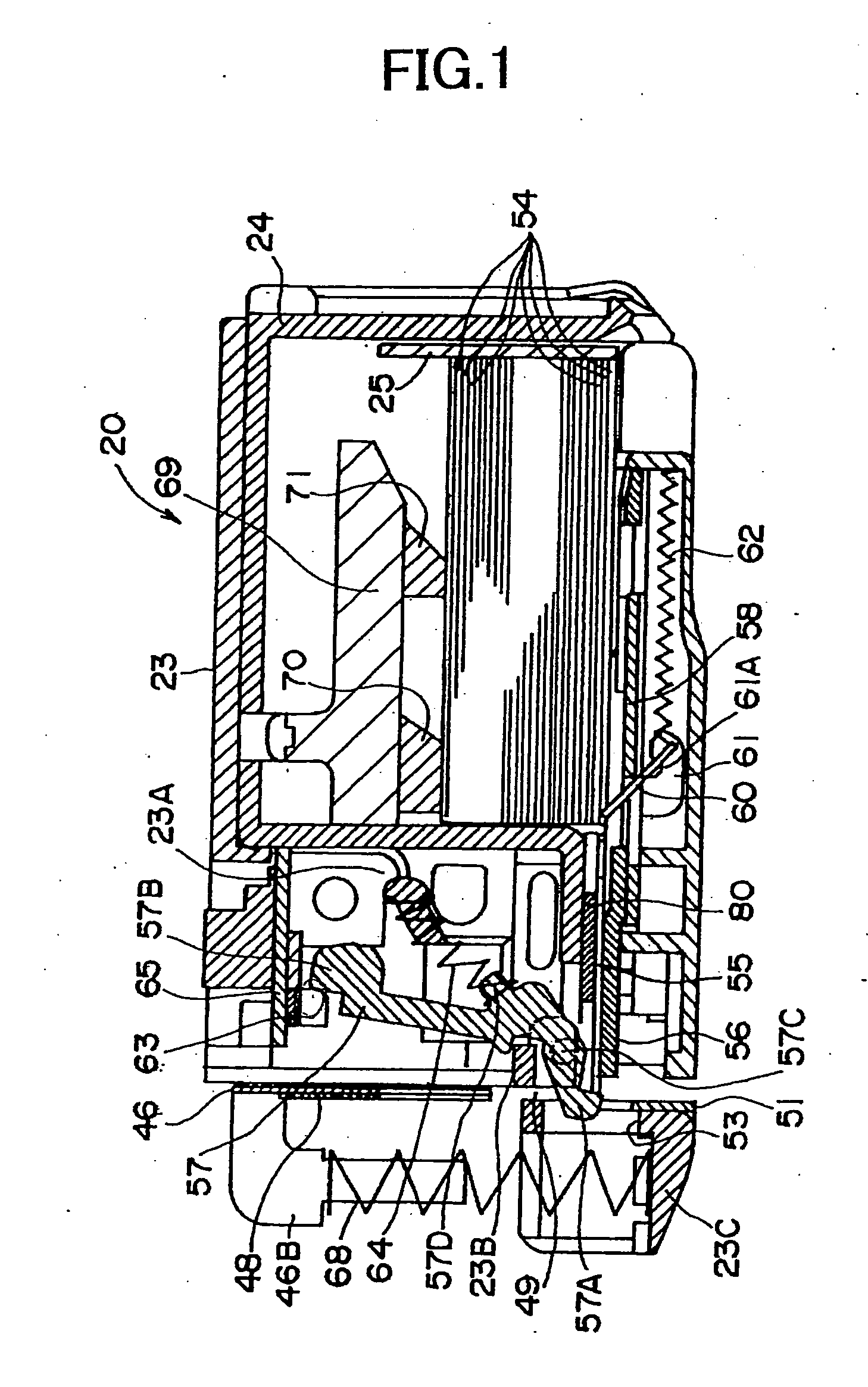
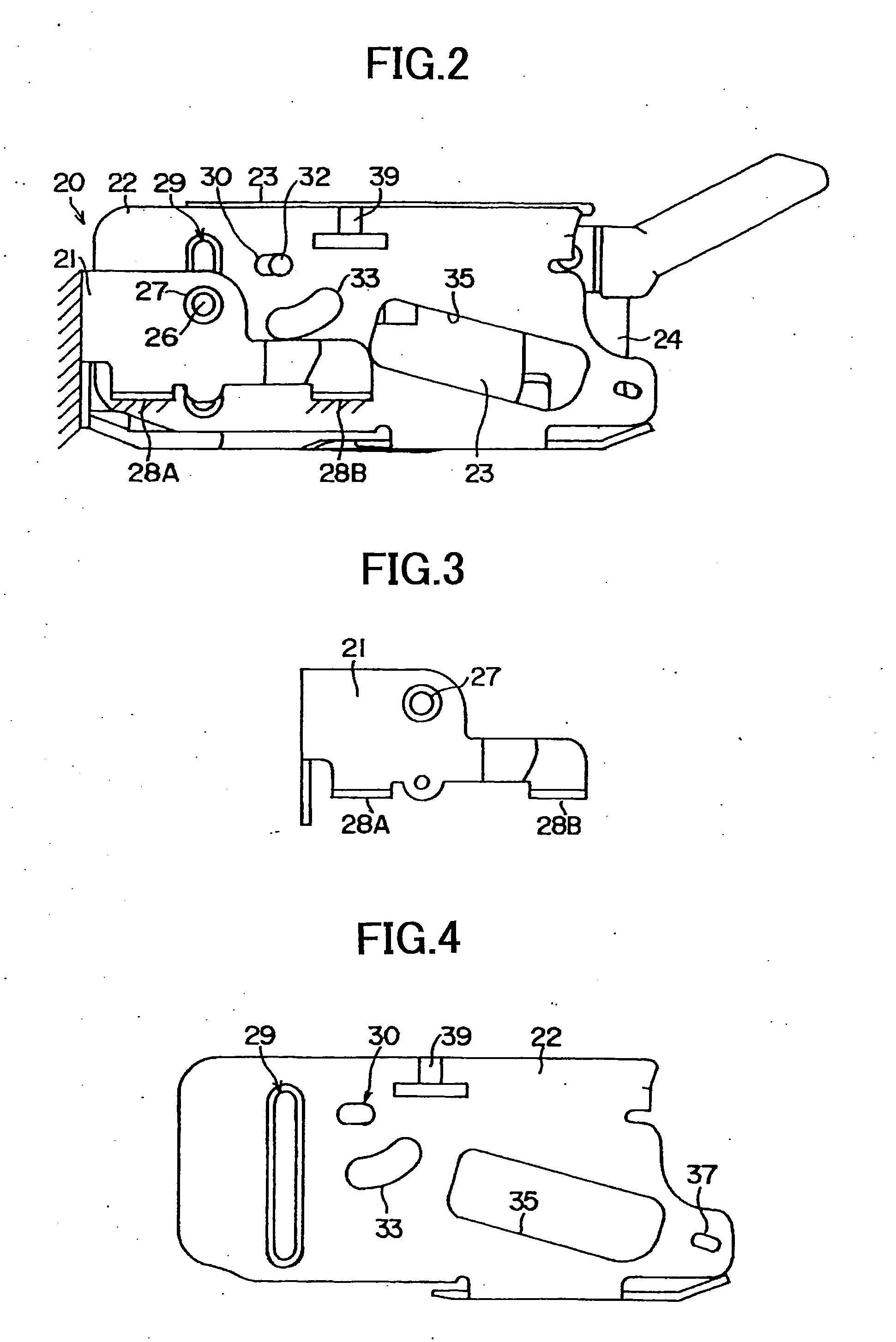
[0037] FIG. 2 shows an outlined construction of the electric stapler according to one embodiment. In FIG. 2, a reference numeral 20 shows an electric stapler. The electric stapler 20 comprises an outer casing 21 fixedly attached to a frame of a stacking mechanism of a copying machine, an inner casing 22 vertically movably supported by the outer casing 21, a magazine 23 swingably held in the inner casing 22, a cartridge casing 24 fitted into the magazine 23, and a cartridge 25 (See FIG. 1) received in the cartridge casing 24.

[0038] The outer casing 21 has a one side-opened rectangular planar shape to house the inner casing 22. As shown in FIGS. 3 and 9, a side plate of the outer casing 21 is provided with a fitting hole 27 for a guide pine 26. The outer casing 21 has projecting pieces 28A and 28B proje


PUM

PropertyMeasurementUnit
Electric chargeaaaaaaaaaa
Currentaaaaaaaaaa
Currentaaaaaaaaaa

Abstract

A staple sheet-detecting mechanism of an electric stapler having its detection accuracy improved and realizing miniaturization thereof is disclosed. According to this staple sheet-detecting mechanism of the electric stapler, a passage 55 is provided for feeding a staple sheet 54 composed of straight forward staples arranged in parallel, and a forming plate 46 and driver 48 are arranged above an anvil 56A of the passage 55. A formed staple 54A is inserted into copy papers located under the staple 54A by moving the forming plate 46 and the driver 48 to a side of the staple 54A. At that place above the anvil 56A where the forming plate 46 waits is provided a sensor (rocking member) 57 of which one end 57A contacts a tip edge of the staple sheet 54 in a feeding direction thereof, while the other end 57B turns on or off an interrupter (detecting element) 63. A rocking fulcrum 57C of the sensor 57 is provided biased to a side of the staple sheet 54 in the passage 55. The forming plate 46 and the driver 48 are provided with recessed portions 46A and 48A, respectively, for allowing the sensor 57 to rock.

Description


Claims


Application Information

Patent Timeline
Owner MAX CO LTD
Why Eureka
Try Eureka