Method for respondent-based real-time survey

a real-time survey and respondent technology, applied in the field of survey methods, can solve the problems inapplicability of complicated skip pattern, and inability to apply to the complex form of skip pattern

Inactive Publication Date: 2005-04-07
KIM JEONG UK
View PDF8 Cites 90 Cited by
  • Summary
  • Abstract
  • Description
  • Claims
  • Application Information

AI Technical Summary

Benefits of technology

The present invention provides a way for clients to monitor their responses over time without interrupting them or requiring multiple trips between different locations. This helps gather data about how well they are doing compared to other surveys conducted earlier. Additionally, there is also provided a system where each person's answer rate is set based on factors like answering costs and openings from previous surveys. By monitoring these variables, researchers can make informed decisions when planning future projects.

Problems solved by technology

The technical problem addressed in this patent text relates to the current methods of measuring and recording subject preferences during survey campaigns, particularly in online services where participants frequently change their locations. These methods involve expensive equipment and human effort, leading to slowdowns and errors. Additionally, these methods lack efficiency and accuracy in identifying subjects and generating reports.

Method used


Image

  • Method for respondent-based real-time survey
  • Method for respondent-based real-time survey
  • Method for respondent-based real-time survey

Examples


Embodiment Construction

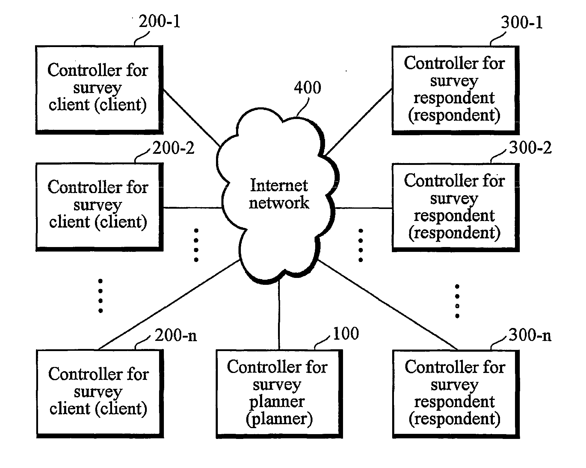
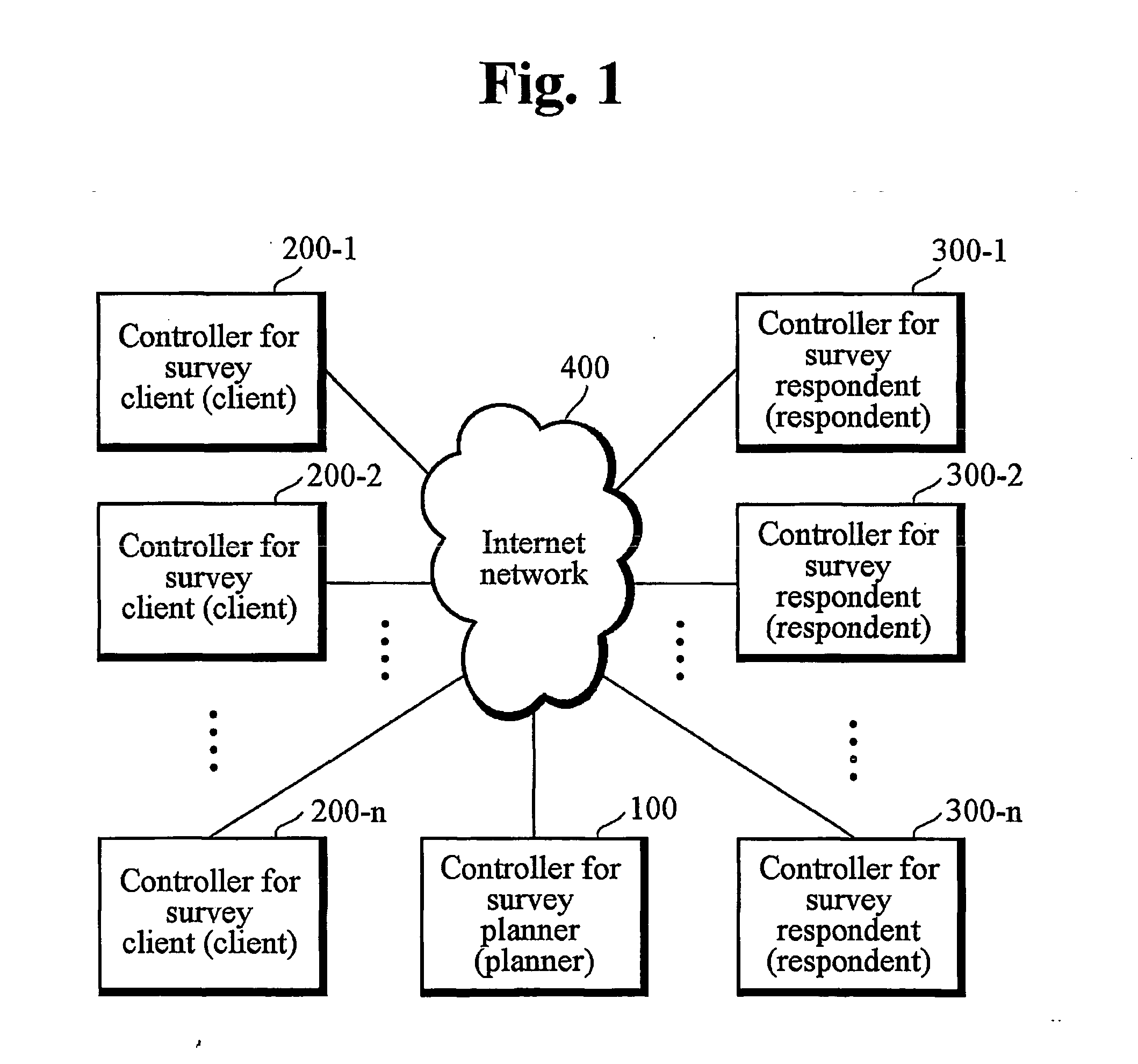
[0031] Hereinafter, a preferred embodiment of the present invention will be described in detail with reference to the accompanying drawings. As shown in FIG. 1, the present invention has the configuration that a central controller 100 for a survey planner, controllers 200-1˜200-n requesting a survey, and controllers 300-1˜300-n for respondents participating in the survey are interconnected with one another through an Internet network 400. It will be readily understood by a person having ordinary skill in the art that the Internet network 400 may be formed by means of general telephone networks, dedicated line networks, wireless networks, satellite networks, microwave networks and the like.

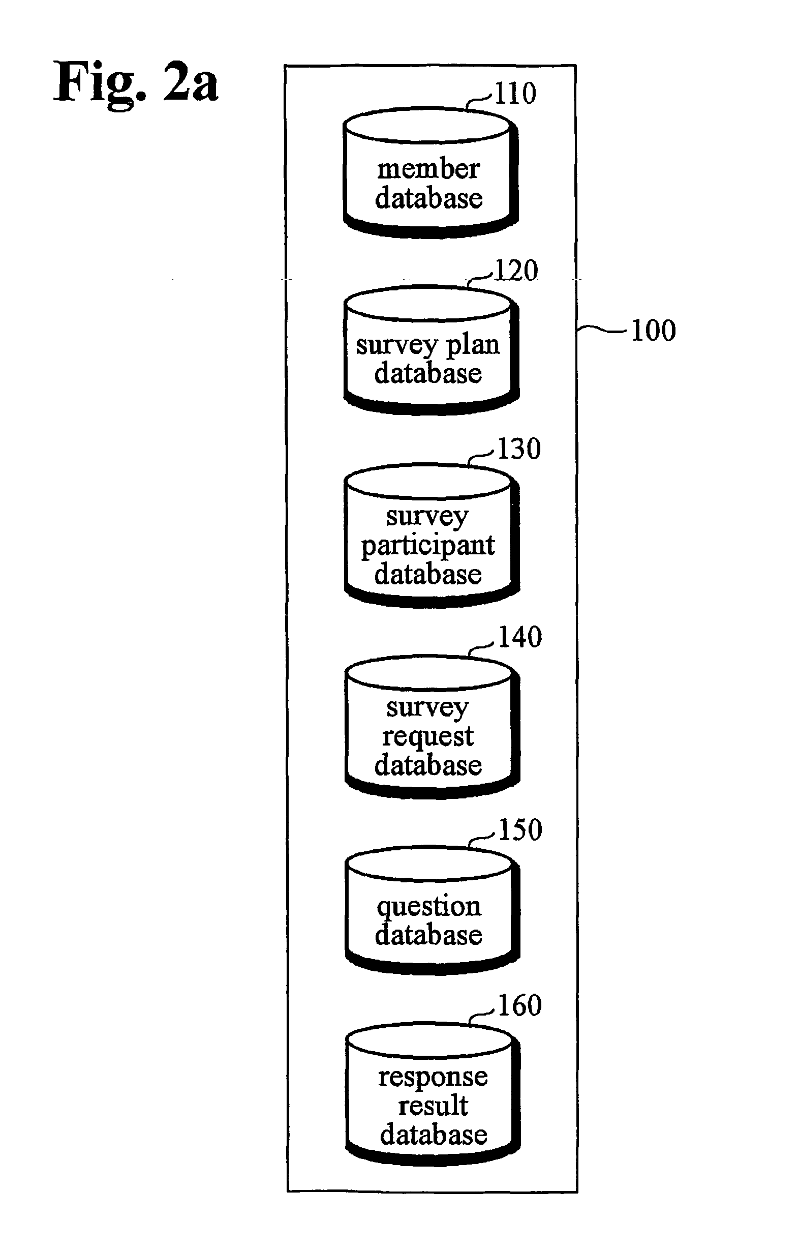
[0032]FIG. 2a shows the types and configurations of databases into which a central controller 100 for a planner of the survey stores information received from a controller 200 (hereinafter, the term “client” may be used for designating “controller for the client”) for a client of a survey and a contr


PUM


Abstract

The present invention relates to a method of conducting a respondent-driven survey in real time. An object of the present invention is to provide a real time and bi-directional respondent-driven survey method comprising the steps of forming a community composed of many respondents having common characteristics through an Internet network at the same period of time, requesting a purchase (survey request) in a predetermined time range by plural clients who need information on the community, selecting a client who provides the best condition among the plural clients, receiving payment from the selected client in real time, conducting the survey required by the client on the community in real time, and analyzing the collected results of the survey to be sent to the client.

Description


Claims


Application Information

Patent Timeline
Owner KIM JEONG UK
Why Eureka
Try Eureka