Bird feeder guard

Inactive Publication Date: 2005-09-29
OPUS
View PDF6 Cites 5 Cited by
  • Summary
  • Abstract
  • Description
  • Claims
  • Application Information

AI Technical Summary

Benefits of technology

[0007] In one embodiment, the present invention is directed toward a bird feeder. In one aspect, the feeder comprises a housing that defines a feed chamber. This housing includes a lid, wherein the lid has at least one opening. This opening can be used by birds to access food within the feeder. In another aspect, the feeder of the present invention includes one or more guard units. The guards are formed integrally with the lid near or at an opening. In one aspect, the guards include an occluding element, wherein this occluding el

Problems solved by technology

Insect feeding and contamination is another familiar problem especially with nectar feeders.
However, these moats are not always successful in thwarting off the persistence of insects.
Moreover, these moats require constant attention such as refilling and unpleasant cleaning.
However, there are problems associated with

Method used


Image

  • Bird feeder guard
  • Bird feeder guard
  • Bird feeder guard

Examples


Embodiment Construction

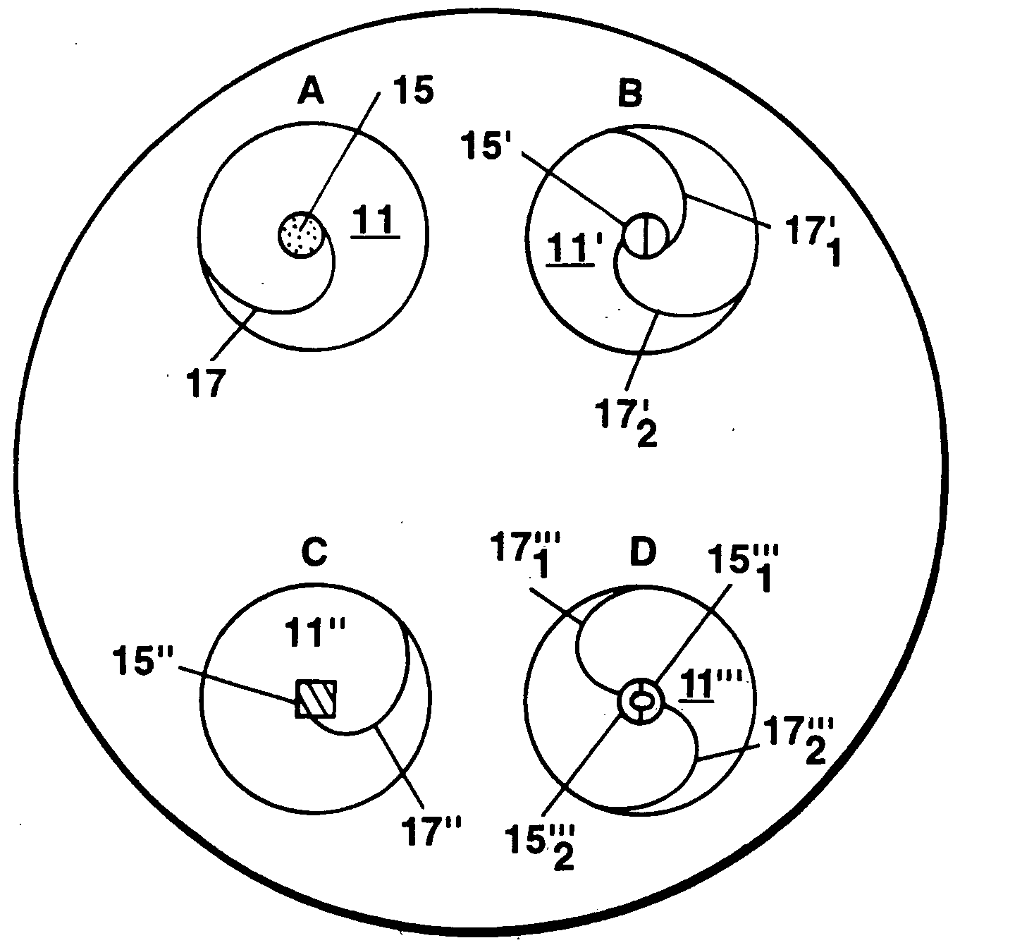
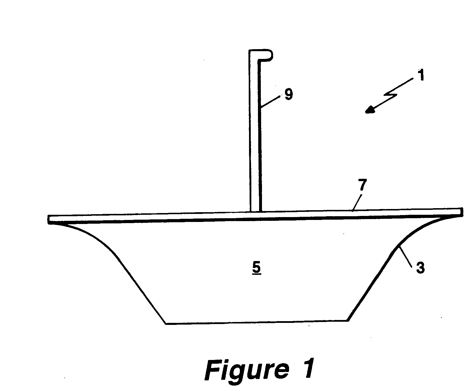
[0013] The present invention relates to a bird feeder. In particular, the invention pertains to a bird feeder guard that serves as a barrier to contaminating animals, including insects, from entering a feed chamber of a bird feeder.

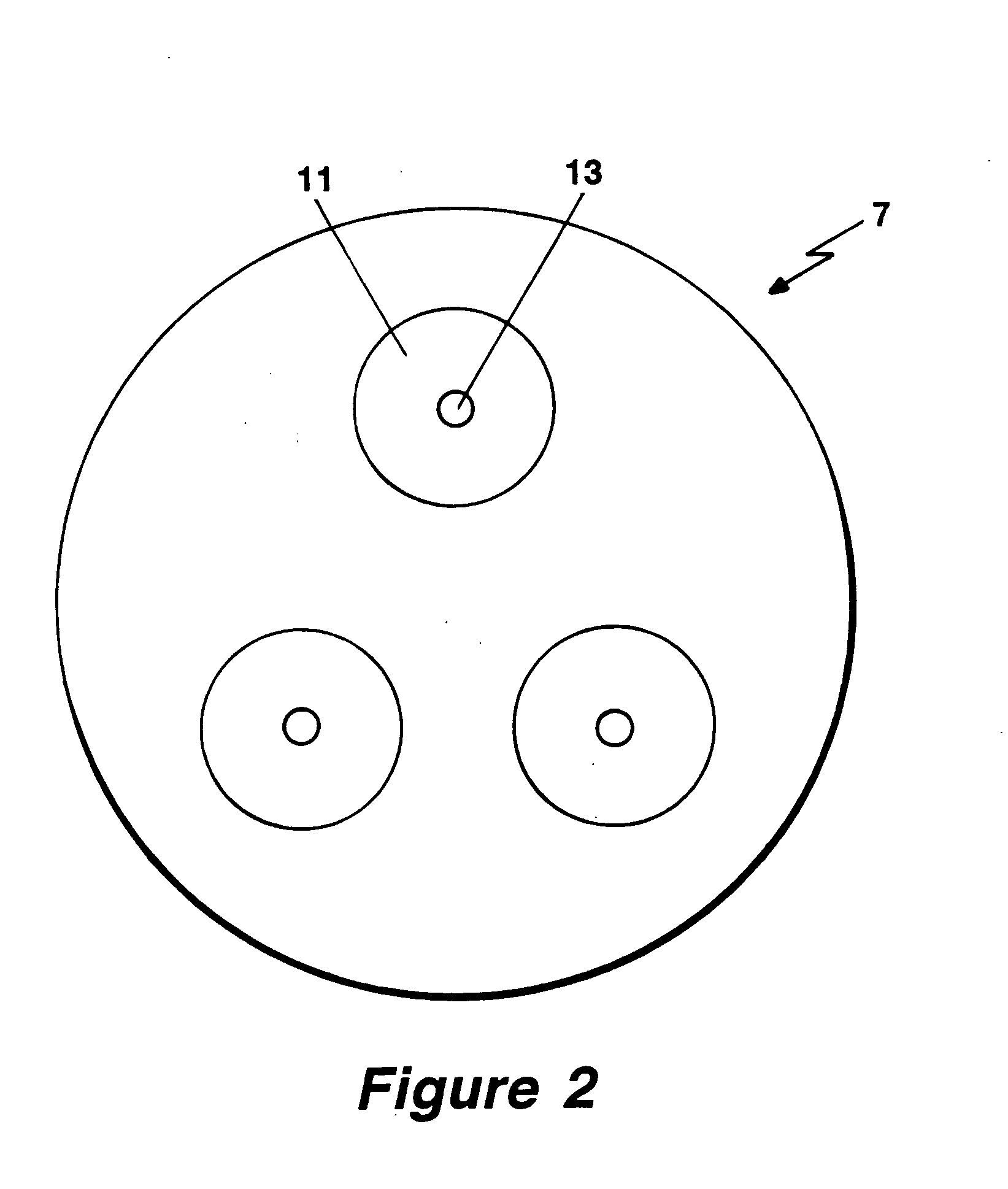
[0014] The bird feeder 1 of the present invention includes a housing 3 which defines a chamber 5. The chamber 5 houses food for birds, for example, nectar. See FIG. 1. The feeder 1 further includes a lid 7 that sits atop the housing 3. In one aspect, the housing 3 is defined by three surfaces. There is a basement surface and at least two lateral surfaces. The basement surface is disposed toward the “bottom” direction, as depicted in FIG. 1. (The terms “top” and “bottom” are arbitrary and are used only for the convenience of the reader.) The volume of the chamber 5 varies. For example, the volume of the chamber 5 can range from about 470 mL to about 960 mL. In one aspect of this embodiment, the feeder 1 includes a stalk 9 in order to suspend or otherwise att


PUM


Abstract

Disclosed herein is a bird feeder with a guard protecting against contamination of the bird feed contained within the feeder. The feeder comprises a housing that defines a feed chamber. This housing includes a lid, wherein the lid has at least one opening. This opening can be used by birds to access food within the feeder. As mentioned above, the feeder includes a guard. This guard is formed integrally or it can be a separate part attached to the lid near or at an opening. In one aspect, the guard includes an occluding element, wherein this occluding element is in communication with a biasing element. The occluding element has a first position which occludes an opening sufficiently to prevent animals other than certain birds from gaining access to said feed chamber. This occluding element is capable of being movable to a second position by applied external pressure to the occluding element thus permitting access to said chamber. As the applied pressure is withdrawn, the occluding element substantially returns to its first position.

Description


Claims


Application Information

Patent Timeline
Owner OPUS
Why Eureka
Try Eureka