Voltage controlled oscillator with linear capacitance

Inactive Publication Date: 2006-01-26
COMMISSARIAT A LENERGIE ATOMIQUE ET AUX ENERGIES ALTERNATIVES
View PDF8 Cites 6 Cited by
  • Summary
  • Abstract
  • Description
  • Claims
  • Application Information

AI Technical Summary

Benefits of technology

[0014] The object of the invention is to overcome these drawbacks and, more particularly, to achieve a voltage controlled oscillator having a linea

Problems solved by technology

Switching from one standard to the other, i.e. from one frequency band to another, can cause pulling out of synchronism of the phase lock loop, i.e. the voltage controlled oscillator no longer supplies any signal.
This technique enables a linear capacitance/voltage characteristic to be obtained but the gain of the oscillator is, in this case, very high and the phase noise is therefore great.
In addition, as the voltage range is reduced, loop-locking of a phase lock loop is more difficu

Method used


Image

  • Voltage controlled oscillator with linear capacitance
  • Voltage controlled oscillator with linear capacitance
  • Voltage controlled oscillator with linear capacitance

Examples


Embodiment Construction

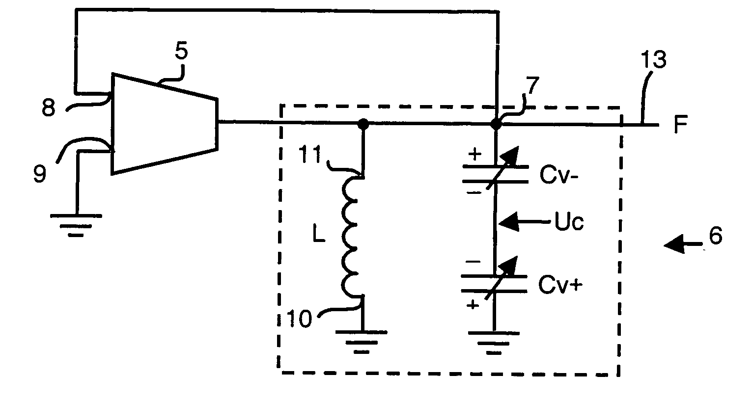
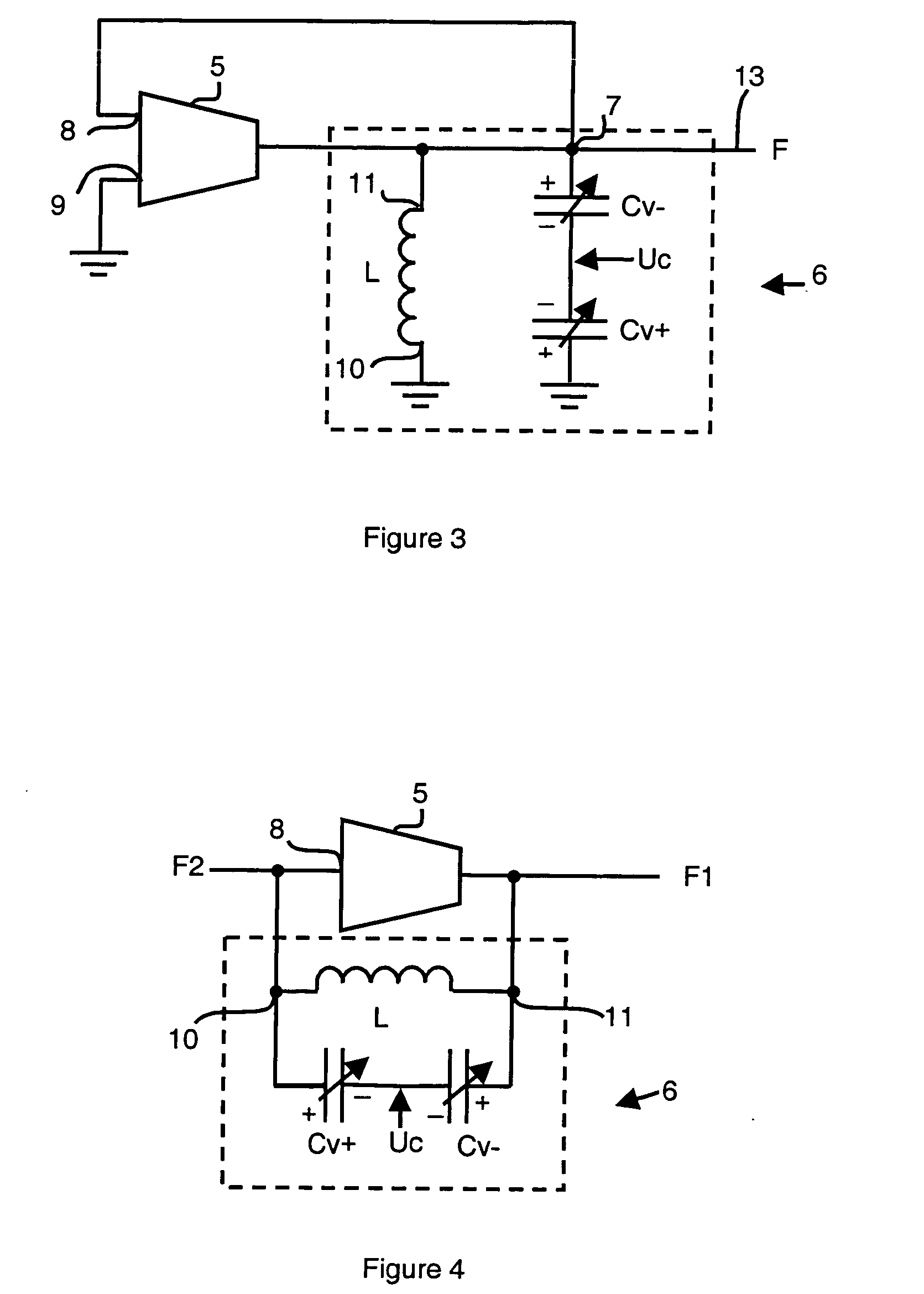
[0022] The voltage controlled oscillator 1 represented in FIG. 3 is an oscillator with a single output 13 which comprises an amplifier 5 and an oscillating system 6, of LC type, connected according to FIG. 2.

[0023] Thus, the first terminal 10 of the inductor L is grounded and the second terminal 11 of the inductor L is connected to the output of the amplifier 5. The second terminal 11 of the inductor L is also connected to the feedback terminal 7 connected to the first input 8 of the amplifier 5. The second input 9 of the amplifier is grounded.

[0024] The oscillating system 6 comprises a first variable capacitor Cv+ and a second variable capacitor Cv− connected in series between the feedback terminal 7 and ground. In the particular embodiment represented, the inductor L is thus connected in parallel with the first variable capacitor (Cv+) and the second variable capacitor (Cv−). A positive terminal of the first variable capacitor Cv+is grounded and a positive terminal of the second va


PUM


Abstract

The voltage controlled oscillator comprises an amplifier and an oscillating system comprising an inductor and a first and second variable capacitor connected in series, each having a capacitance varying according to its control voltage. The capacitance of one of the variable capacitors varies in the same direction as its control voltage and the capacitance of the other variable capacitor varies in the opposite direction to its control voltage. A capacitor having a fixed capacitance can be connected in series or in parallel with the first and second variable capacitors. The first and second variable capacitors are preferably formed by transistors, respectively of PMOS and NMOS type. An additional series of additional first and second variable capacitors can be connected in parallel with the first and second variable capacitors.

Description


Claims


Application Information

Patent Timeline
Owner COMMISSARIAT A LENERGIE ATOMIQUE ET AUX ENERGIES ALTERNATIVES
Why Eureka
Try Eureka