Vehicle mount assembly for a utilitarian accessory

Inactive Publication Date: 2006-03-16
CURTIS IND INC
View PDF99 Cites 25 Cited by
  • Summary
  • Abstract
  • Description
  • Claims
  • Application Information

AI Technical Summary

Benefits of technology

[0009] The problems of the prior art have been overcome by the present invention, which provides a hitch mount assembly for snow blades or other accessories or implements for vehicles such as pick-up trucks and off-road vehicles such as utility task vehicles. The present invention includes an implement assembly readily removably coupled to the v

Problems solved by technology

Conventionally, the lift frame has been permanently mounted to the chassis frame (and therefore not readily removable from the vehicle), and the hydraulic pump used to operate the snow blade was located under the vehicle hood, and were driven using a belt drive driven by the vehicle engine.
However, safety considerations now often dictate that the lift frame be removed when the plow is not in use.
Moreover, such a location is also no longer feasible since there is little room there to accommodate the pump, and since most vehicles today use a single serpentine belt, again eliminating the feasibility of driving the hydraulics with a belt driven by the vehicle engine.
This arrangement hinders air flow to the vehicle engine, often resulting in engine overheats.
One drawback of conventional snow blade mounts is the difficulty in readily removing the lift frame assemblies from the vehicle ch

Method used


Image

  • Vehicle mount assembly for a utilitarian accessory
  • Vehicle mount assembly for a utilitarian accessory
  • Vehicle mount assembly for a utilitarian accessory

Examples


Embodiment Construction

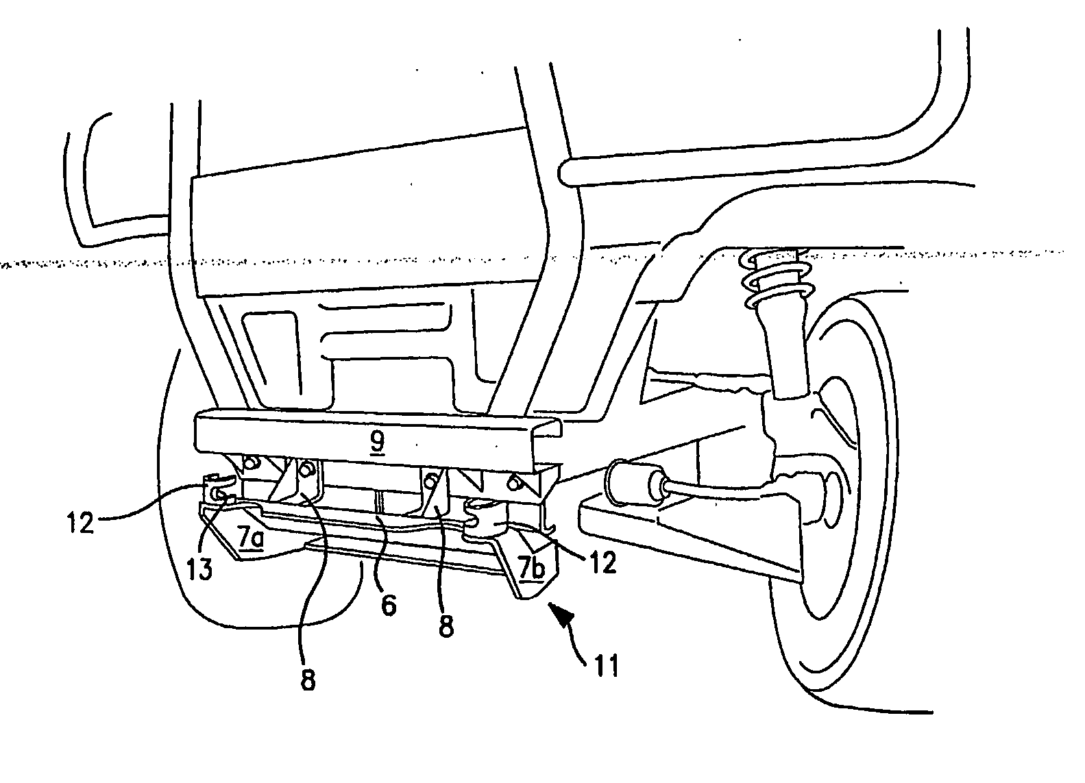
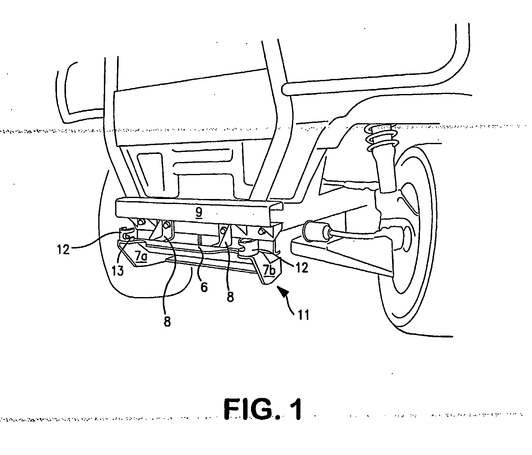
[0022] Turning first to FIG. 1, there is shown generally the receiver assembly in accordance with a preferred embodiment of the present invention. It is preferably made of durable, lightweight material, such as metal, steel, stainless steel, plastics or composites, for example, depending upon the relative strength required of each component. Vehicle mounted receiver 11 attaches to the vehicle chassis or frame, or is integrated therewith. Any Suitable means can be used to secure the receiver 11 to the vehicle, such as bolting or manufacturing integration (e.g., as a stamped component of the vehicle chassis or frame). For example, the receiver 11 can include a pair of brackets 8 with holes for coupling the receiver to the vehicle chassis, such as an existing frame 9 on a UTV. The design of the receiver 11 interface for attachment to the chassis will depend upon the identity (and thus design) of the particular chassis, and is well within the skill in the art. Because in the embodiment sho


PUM


Abstract

Hitch mount assembly for snow blades or other accessories or implements for pick-up trucks or off-road vehicles such as utility task vehicles. The assembly includes a receiver for mounting to the vehicle chassis and an implement assembly readily removably coupled to the receiver. The configuration of the receiver and implement assembly allows for selfalignment during the mounting operation. One or more over center latches draw the receiver and mounting assembly together.

Description


Claims


Application Information

Patent Timeline
Owner CURTIS IND INC
Why Eureka
Try Eureka