Misfire detector for multi-cylinder engine

Active Publication Date: 2006-06-01
SUZUKI MOTOR CO LTD
View PDF1 Cites 24 Cited by
  • Summary
  • Abstract
  • Description
  • Claims
  • Application Information

AI Technical Summary

Benefits of technology

[0025] Further, in the misfire detector for the multi-cylinder engine having the misfire detecting means to detect the misfire for each cylinder, and performing the misfire control if the frequency of the misfire detected by the misfire detecting means is more than the predetermined value, the misfire control includes (1) the fuel cut control for misfire cylinders by the fuel cut means to stop supplying the fuel to the misfire cylinders, (2) a control to prevent the fuel feed back control and the fuel leaning control and to initialize the correction values of both the fuel feed back control and the fuel leaning control, and (3) the engine speed control to limit the engine speed below the predetermined engine speed irrespective of the opening degree of the acceleration. Accordingly, when the misfire is detected, a rise is avoided in the catalyst temperature owing to the driving at high speed under heavy engine load in a situation where the driver depresses the acceleration pedal when he feels power down due to the misfires. This prevents detriment or damage of the catalyst.
[0026] Furthermore, in the misfire detector for the multi-cylinder engine having the misfire detecting means to detect the misfire for each cylinder, and performing the misfire control if the frequency of the misfire detected by the misfire detecting means is more than the predetermined value, the misfire control includes (1) the fuel cut control for misfire cylinders by the fuel cut means to stop supplying the fuel to the misfire cylinders, (2) the control to prevent the fuel feed back control and the fuel leaning control and to initialize the correction values of both the fuel feed back control and the fuel leaning control, and (3) the vehicle speed control to limit the engine speed below the predetermined speed irrespective of the opening degree of the acceleration. Accordingly, when the misfire is detected, the driver is prevented from driving at high speed which is contrary to the misfire control for avoiding problems resulting from the misfires. Thereby, the catalyst is not heated to high temperatures, which prevents detriment or damage of the catalyst.
[0027] According to the present invention, when the misfire control is performed, executed are (1) the fuel cut control for misfire cylinders by the fuel cut means to stop supplying the fuel to the misfire cylinders, (2) the control to prevent the fuel feed back control and the fuel leaning control and to initialize the correction values of both the fuel feed back control and the fuel leaning control, and (3) the retard control to retard the ignition timing by the retard quantity set based on

Problems solved by technology

In an engine mounted on a vehicle, there may be caused misfires due to unstable combustion of the fuel in a combustion chamber due to various factors such as lean mixture of the air-fuel ratio by driving under lean combustion, a malfunction of ignition systems or fuel systems, and a failure of components of the engine.
When misfire of the engine occurs, unburned gas flows to the catalyst in the exhaust system and burns which cau

Method used


Image

  • Misfire detector for multi-cylinder engine
  • Misfire detector for multi-cylinder engine
  • Misfire detector for multi-cylinder engine

Examples


second embodiment

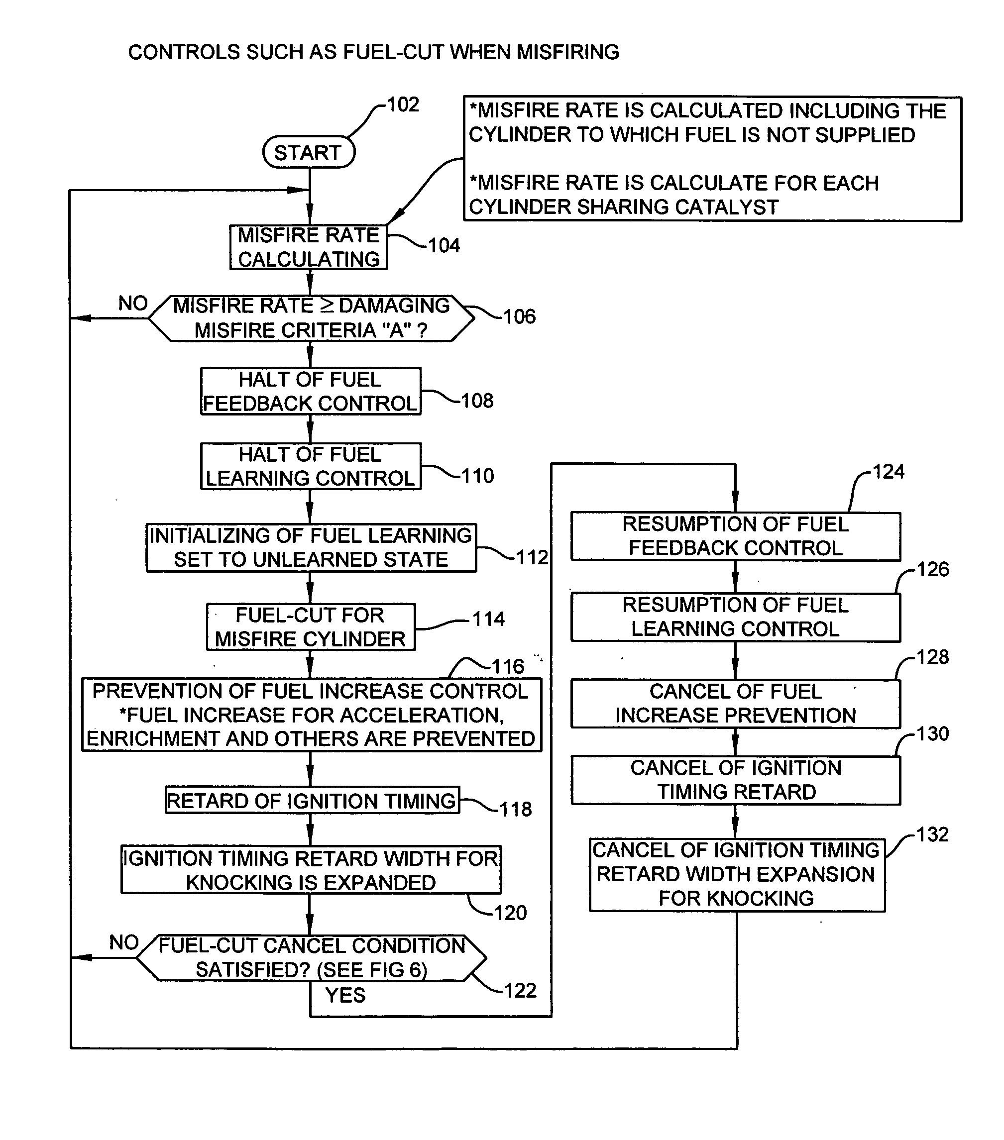
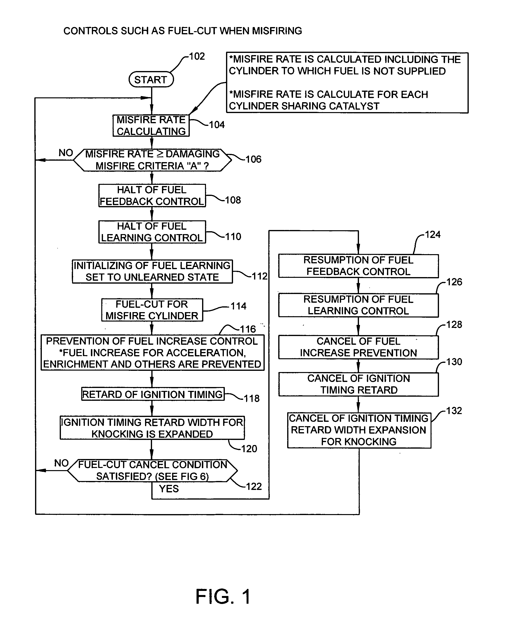
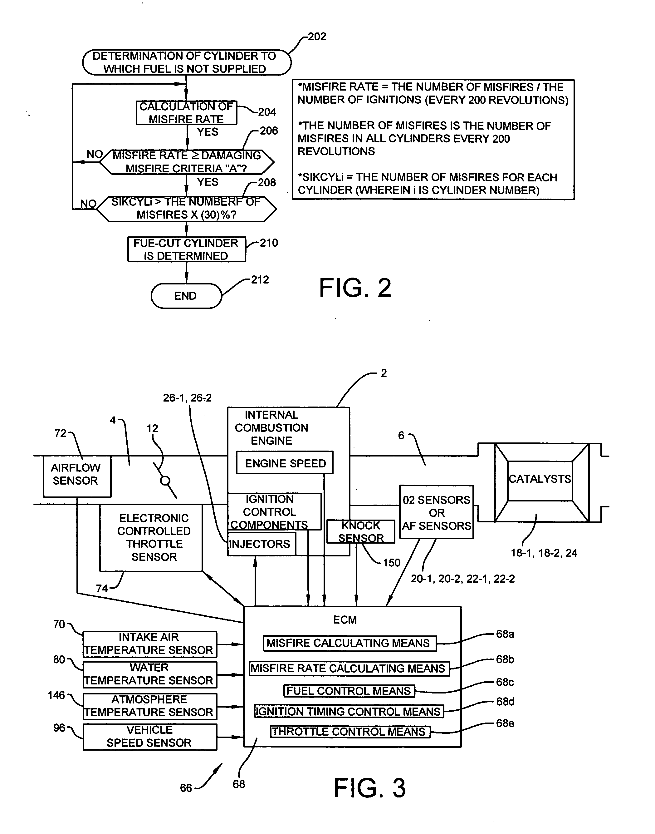
[0096] Operation of the second embodiment is explained with reference to a flowchart of FIG. 8 for throttle control of the misfire detector when misfiring. A program for the throttle control for misfire starts in step 302. The rate of misfire for each cylinder is calculated in step 304. Then a determination is made in step 306 as to whether this misfire rate is greater than or equal to the damaging misfire criteria A at which the catalyst may be damaged.

[0097] The rate of misfire is calculated for every 200 revolutions of the engine speed for each cylinder. This calculation includes the cylinder for which the fuel cut is performed. For the V-type engine, the misfire rate is calculated for each cylinder bank. Also, the misfire rate is calculated for each cylinder that shares the catalyst. The damaging misfire criteria A is calculated from a table based on the engine speed and the engine load (see FIG. 5).

[0098] In the determination in step 306 as to whether the misfire rate is greater

third embodiment

[0104]FIGS. 11 and 12 illustrate the present invention.

[0105] The third embodiment of the present invention is characterized in that in the misfire detector for the multi-cylinder engine, the misfire control includes (1) the fuel cut control for misfire cylinders by the fuel cut means to stop supplying the fuel to the misfire cylinders, (2) the control to prevent the fuel feed back control and the fuel leaning control and to initialize the correction values of both the fuel feed back control and the fuel leaning control, and (3) an engine speed control to limit the engine speed below a predetermined engine speed irrespective of the opening degree of the acceleration. Alternatively, the third embodiment of the present invention is characterized in that in the misfire detector for the multi-cylinder engine, the misfire control includes (1) the fuel cut control for misfire cylinders by the fuel cut means to stop supplying the fuel to the misfire cylinders, (2) the control to prevent the f


PUM


Abstract

The purpose of the present misfire detector is to prevent catalysts from being heated to high temperatures, thereby avoiding detriment or damage of the catalysts. The misfire detector for a multi-cylinder engine includes (1) a fuel cut control for misfire cylinders by a fuel cut means to stop supplying the fuel to the misfire cylinders, (2) a control to prevent a fuel feed back control and a fuel leaning control and to initialize the correction values of both the fuel feed back control and the fuel leaning control, and (3) a retard control to retard the ignition timing by a retard quantity set based on the extent the misfire occurs or the air-fuel ratio. The above control (3) can be replaced by a throttle opening control for misfire to limit the throttle opening angle as compared to a normal opening in accordance with the acceleration degree. The above control (3) can also be replaced by an engine speed control to limit the engine speed below a predetermined engine speed irrespective of the opening degree of the acceleration. Further, the above control (3) can be replaced by a vehicle speed control to limit the vehicle speed below a predetermined speed irrespective of the opening degree of the acceleration.

Description


Claims


Application Information

Patent Timeline
Owner SUZUKI MOTOR CO LTD
Why Eureka
Try Eureka