Luggage wheel system

Inactive Publication Date: 2006-09-21
SHER MOU ONG
View PDF13 Cites 15 Cited by
  • Summary
  • Abstract
  • Description
  • Claims
  • Application Information

AI Technical Summary

Benefits of technology

[0005] It is therefore an object of the present invention to provide an improved luggage wheel system having a rear fender mounted over the wheel o

Problems solved by technology

It is typical that a luggage user may lift the luggage when wheels encounter an irregularity (e.g., crack, pebble) in the supporting

Method used


Image

  • Luggage wheel system
  • Luggage wheel system
  • Luggage wheel system

Examples


Embodiment Construction

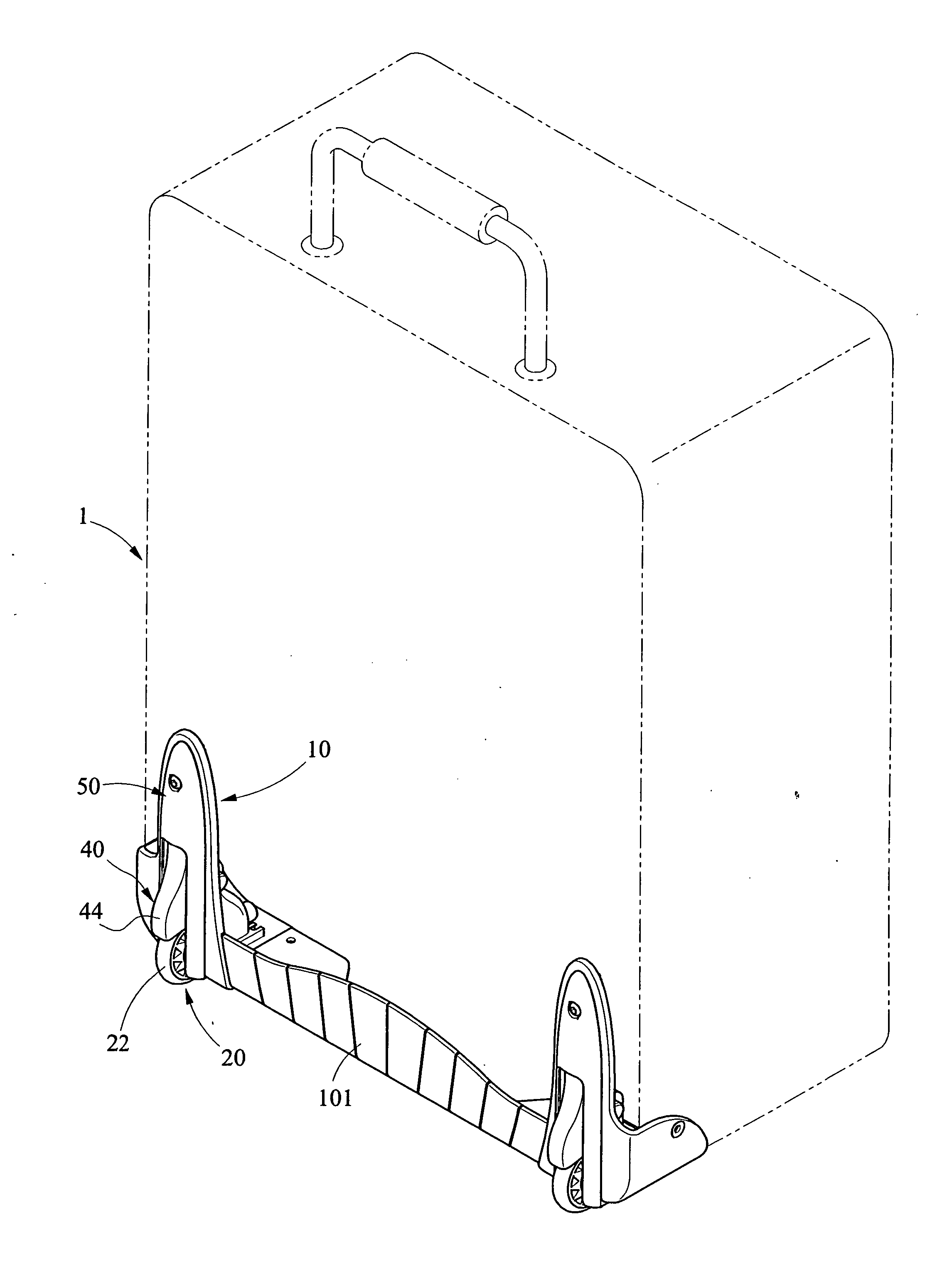
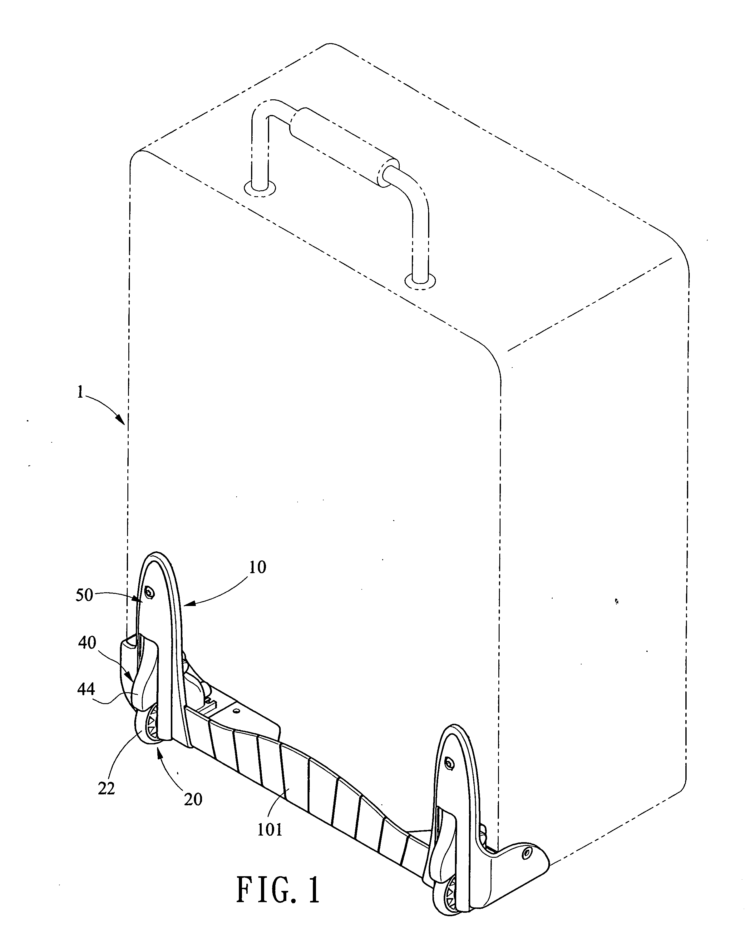
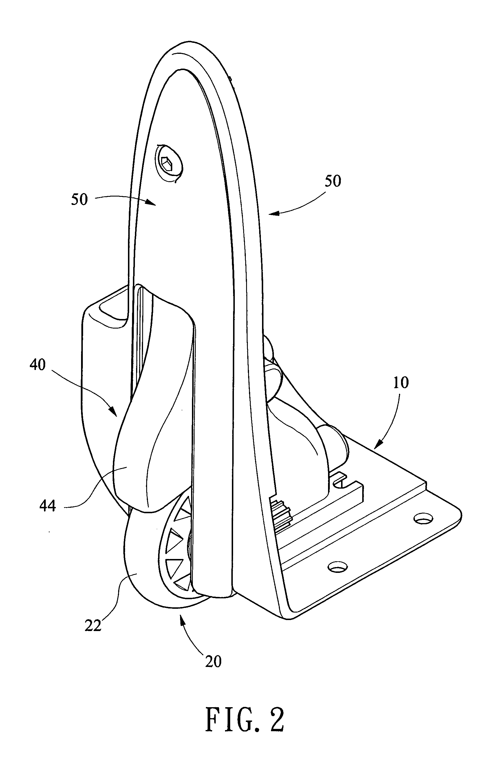
[0019] Referring to FIGS. 1 to 4, there is shown a first preferred embodiment of the invention. A wheel system of a luggage 1 is located at either corner of its rear portion and comprises a bracket 10, a wheel assembly 20, a resilient assembly 30, a fender 40, and a wheel mount 50. Each component is discussed in detailed below. The bracket 10 is secured to the luggage bottom shell 101 by driving either a fastener (e.g., screw, bolt and nut combination, or rivet) through a hole 102 as known in the art or a toothed member 16 through the hole 102. The bracket 10 further comprises a lower well 11 including two upper side recesses 111 at its upper portion, two lower side cavities 112 at its lower portion, two side channels 113 each extended from the recess 111 to the cavity 112 at the same side, and a hole 114 on an inner wall, the hole 114 having a blind end and being substantially parallel to the cavities 112; a latch 12 disposed above the well 11; two grooves 13 at both sides of the latc


PUM


Abstract

Provided is a luggage wheel system mounted at either rear corner of a luggage case, comprising a bracket fixedly secured to the luggage case, a spring-loaded wheel assembly rotatably disposed in the bracket, and a fender slidably disposed in a front portion of the bracket and above the wheel assembly in a nonoperating position. In a case of the wheel to be encountered an irregularity (e.g., crack, pebble) in the supporting surface a luggage user may lower the fender to disengage a top bent member of the fender with a latch in a wheel mount for covering a rear, upper half portion of the wheel. As an end, cuff of trousers worn by the luggage user is prevented from becoming dirty by contacting the wheel when lifting the luggage.

Description


Claims


Application Information

Patent Timeline
Owner SHER MOU ONG
Why Eureka
Try Eureka