Wireless device

Inactive Publication Date: 2007-01-04
PARTNER TECH
View PDF2 Cites 8 Cited by
  • Summary
  • Abstract
  • Description
  • Claims
  • Application Information

AI Technical Summary

Benefits of technology

This patent describes an improved method for protecting wireless devices that don't receive identifying codes like those used by other devices. It also allows users to switch between sleep modes if they move around without being detected. Users can then use their own keys to activate them again afterward.

Problems solved by technology

This patent describes two technical problem addressed in the patent: how to improve the usability of electronic devices such as laptops and PDAs while still providing physical keys that can be easily carried around with them.

Method used


Image

  • Wireless device
  • Wireless device
  • Wireless device

Examples


Embodiment Construction

[0018] The following detailed description is of the best presently contemplated modes of carrying out the invention. This description is not to be taken in a limiting sense, and is made merely for the purpose of illustrating general principles of embodiments of the invention. The scope of the invention is best defined by the appended claims.

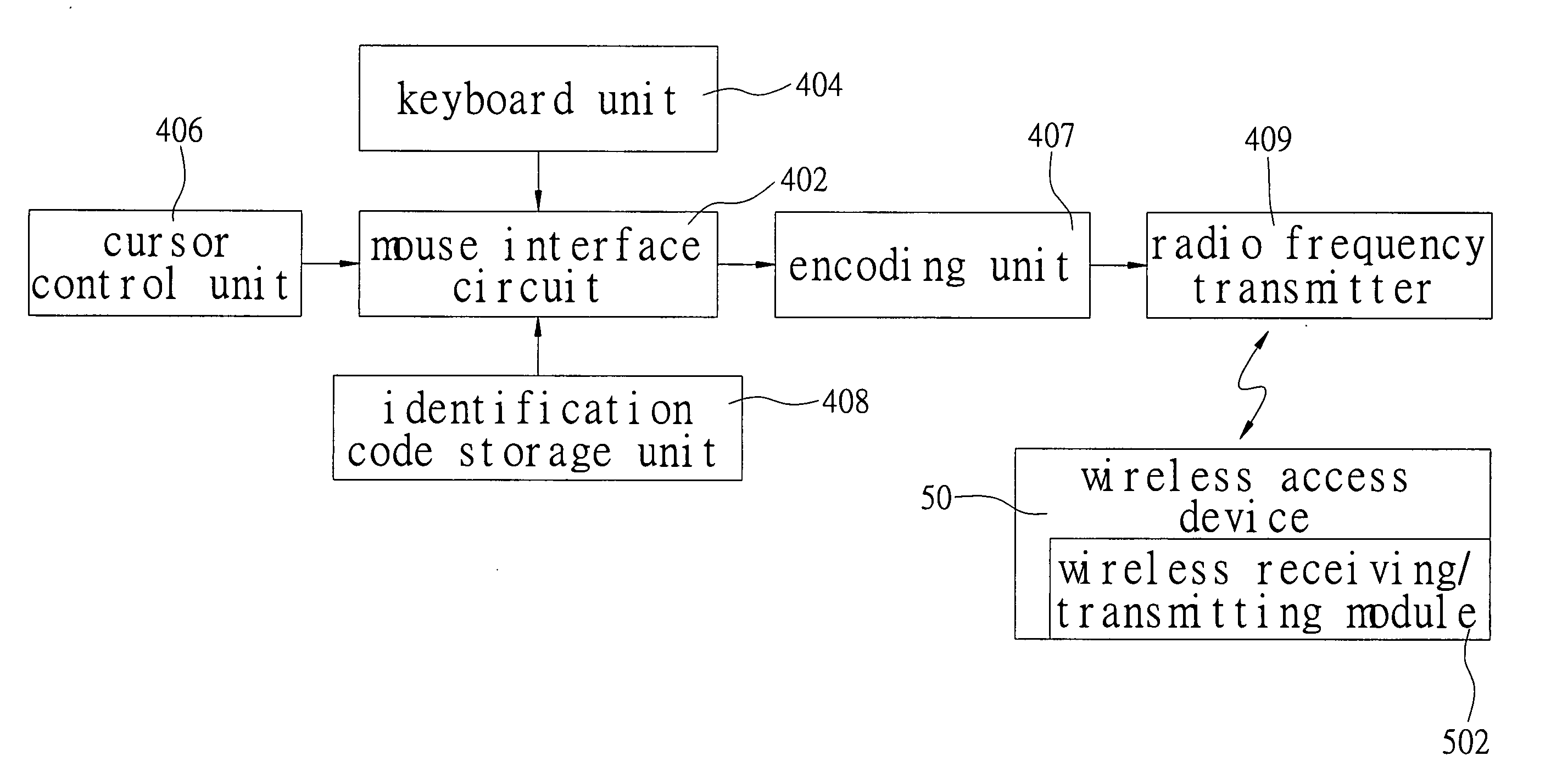
[0019] Reference is made o FIG. 5. FIG. 5 schematically illustrates a block diagram of the present invention. According to the present invention, the wireless device includes a wireless access device 50 having a wireless receiving / transmitting module 502 to receive or transmit wireless signals. The wireless access device 50 can be a notebook computer (notebook) or a personal digital assistant (PDA).

[0020] According to the present invention, the wireless device also includes a wireless stylus 40. The wireless stylus 40 includes a cursor control unit 406, an identification code storage unit 408, a mouse interface circuit 402 and a radio frequency


PUM


Abstract

A wireless device of the present invention has a wireless access device and a wireless stylus. The wireless stylus has a cursor control unit, an identification code storage unit, a mouse interface circuit, and a radio frequency transmitter. The cursor control unit is used to generate a movement signal, and the identification code storage unit is used to store temporarily identification code information. The mouse interface circuit is electrically connected with the cursor control unit and the identification code storage unit. Besides, the mouse interface circuit is used to receive the movement signal and the identification code information to output a cursor control signal and an identification code signal, by signal information processing. The radio frequency transmitter is electrically connected to the mouse interface circuit and used to transmit the cursor control signal and the identification code signal to the wireless access device by wireless communication.

Description


Claims


Application Information

Patent Timeline
Owner PARTNER TECH
Why Eureka
Try Eureka