System and Method for Predicting Mold Growth in an Environment

Inactive Publication Date: 2007-02-01
IAQ LAB INT
View PDF1 Cites 29 Cited by
  • Summary
  • Abstract
  • Description
  • Claims
  • Application Information

AI Technical Summary

Benefits of technology

[0008] Mold growth prediction systems and methods for an environment are disclosed. The system includes a processing unit, a temperature sensor, and a humidity sensor. The processing unit has an interface for obtaining a temperature reading and a humidity reading of the environment from the sensors. The processing unit also has a memory for storing an algorithm to determine a probability of mold growth and has a processor communicatively coupled to the interface and the memory. The processor processes the temperature reading, the humidity reading, and a time reading according to the algorithm to determine the probabili

Problems solved by technology

Molds can grow indoors and can cause various health risks or environmental damage.
Unfortunately

Method used


Image

  • System and Method for Predicting Mold Growth in an Environment
  • System and Method for Predicting Mold Growth in an Environment
  • System and Method for Predicting Mold Growth in an Environment

Examples


Embodiment Construction

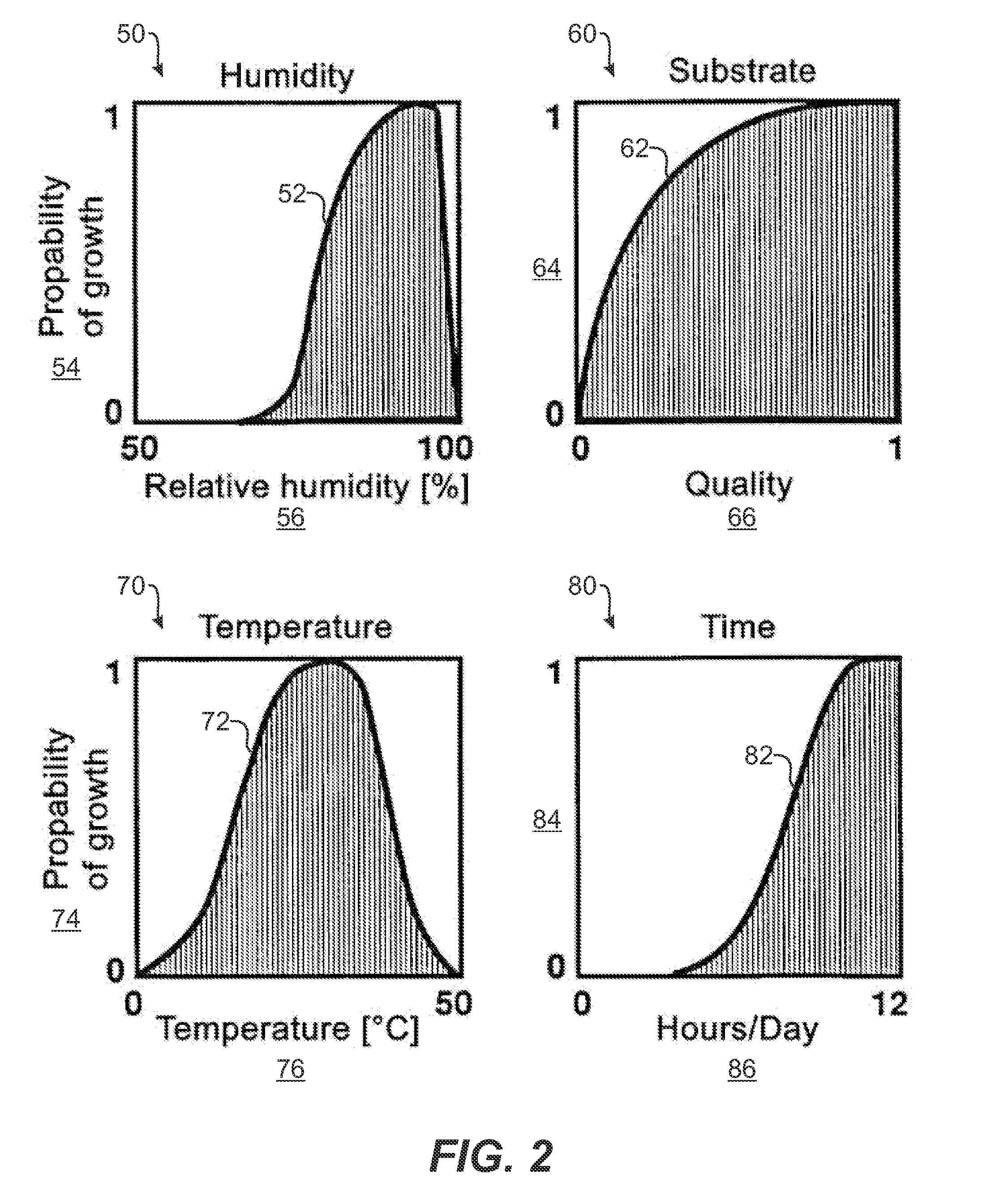
[0034] Referring to FIG. 2, graphs schematically show how four conditions (i.e., relative humidity, temperature, quality, and time) that influence mold growth can be used to determine the probability of mold growth. In the humidity graph 50, for example, curve 52 shows how the probability 54 of mold growth corresponds to relative humidity 56. As shown by curve 52, the probability 54 is practically non-existent when the relative humidity 56 is close to fifty-percent, but the probability 54 increases as the relative humidity 56 is closer to one-hundred percent. At a level of relative humidity 56 quite close to one-hundred percent, the probability 52 of mold growth decreases sharply.

[0035] In the substrate graph 60, for example, curve 62 shows how the probability 64 of mold growth corresponds to the quality 66 of the substrate on which the mold grows. The quality 66 of the substrate refers to the quality of the material that the mold can use for nutrients. Typical substrates include carp


PUM


Abstract

Mold growth monitoring and prediction systems and methods for an environment are disclosed. The system includes a processing unit, a temperature sensor, and a humidity sensor. The processing unit obtains a temperature reading and a humidity reading of the environment from the sensors. The processing unit uses an algorithm to determine a probability of mold growth based on the temperature reading, the humidity reading, and a time reading. For example, the algorithm defines an envelope based on temperature, humidity, and one or more species of mold. The envelope substantially separates conditions detrimental to mold growth from conditions conducive to mold growth for the species of mold. The processing unit uses the algorithm to determine whether the temperature reading and the humidity reading fall within detrimental or conducive conditions to mold growth. Based on the conditions, the processing unit either increases or decreases the probability of mold growth.

Description


Claims


Application Information

Patent Timeline
Owner IAQ LAB INT
Why Eureka
Try Eureka