Signal generating circuit

a signal generation and circuit technology, applied in the direction of oscillator generators, pulse generation with predetermined statistical distribution, pulse techniques, etc., can solve the problem of pop noise generation

Inactive Publication Date: 2007-02-22
LAPIS SEMICON CO LTD
View PDF1 Cites 8 Cited by
  • Summary
  • Abstract
  • Description
  • Claims
  • Application Information

AI Technical Summary

Benefits of technology

This patented technology allows signals generated by electronic devices to be controlled more accurately than previously possible due to its ability to generate stable waveforms without causing any unwanted sounds or vibrations during operation. It uses various techniques like adding extra delays between different parts of the device's circuits to achieve this purpose.

Problems solved by technology

This patented technical problem addressed in this patents relates to improving the accuracy and efficiency of electronic circuits used in communication systems while reducing their size without sacrificing performance or requiring larger storage capabilities.

Method used


Image

  • Signal generating circuit
  • Signal generating circuit
  • Signal generating circuit

Examples


Embodiment Construction

[0017] The embodiment of the invention will be explained using drawings below. The drawings are made briefly for only assisting the understanding of the present invention.

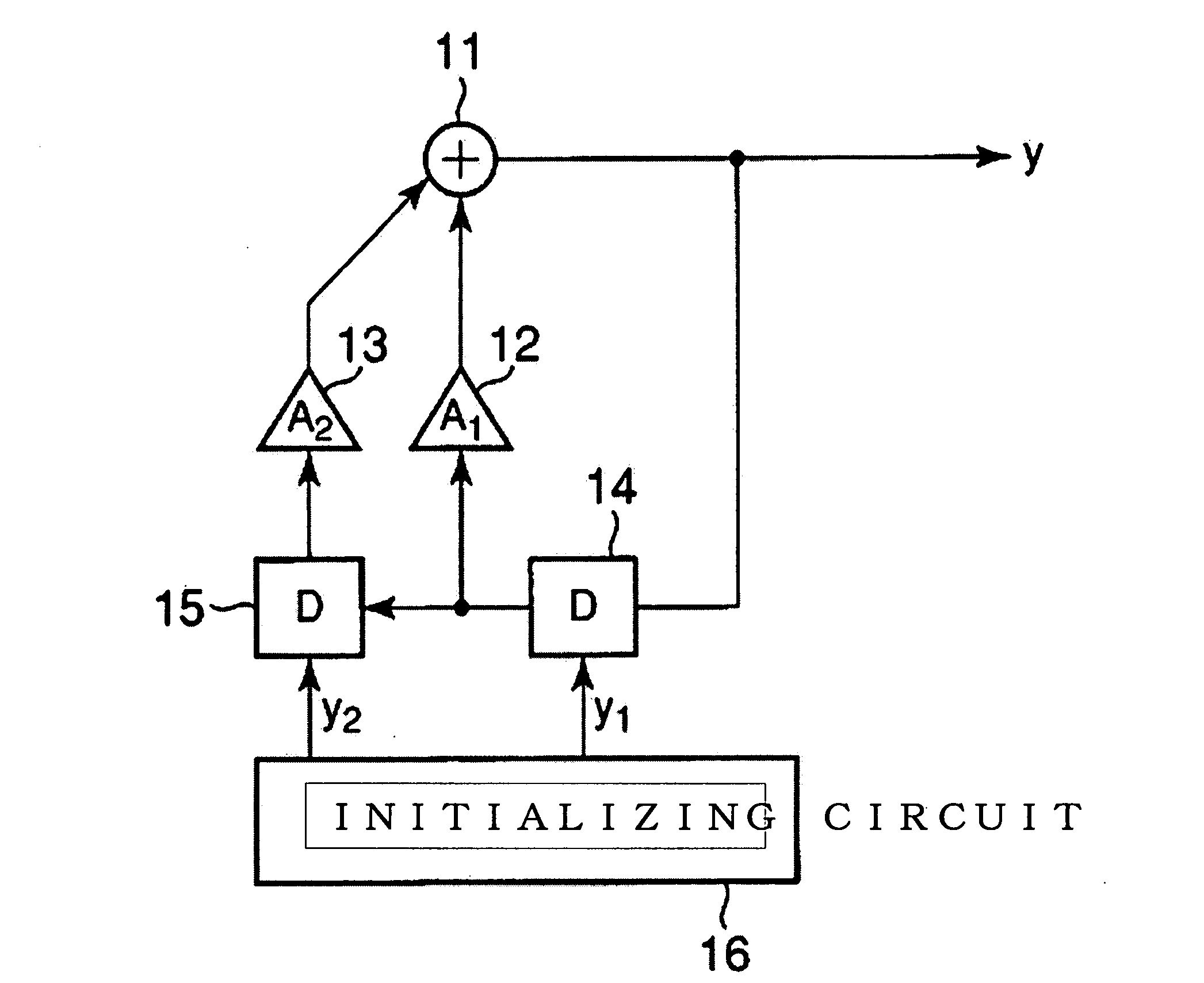
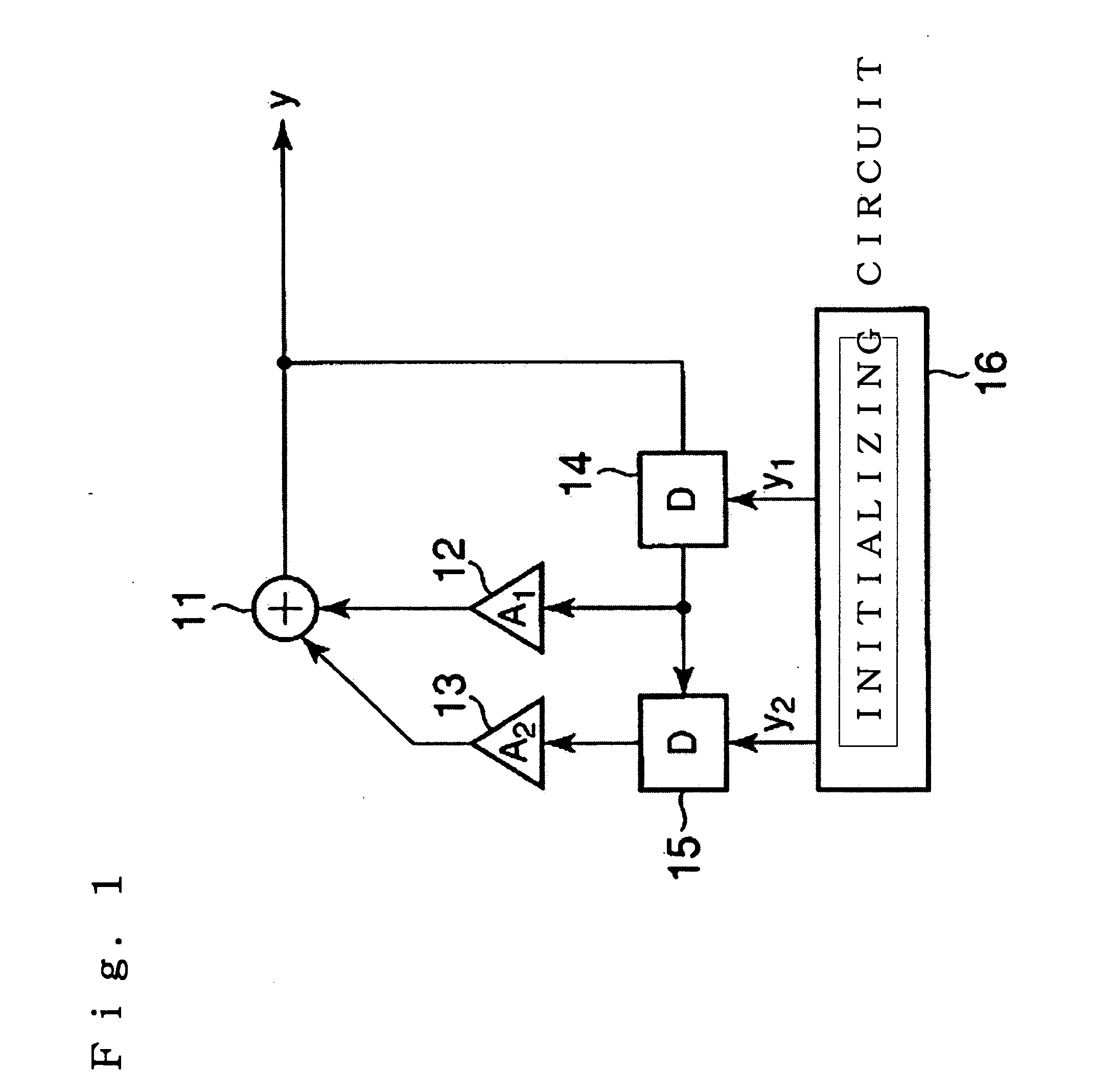
[0018]FIG. 1 shows a configuration diagram of the signal generation circuit in accordance with the embodiment the invention. The circuit includes an adder 11, a first multiplier 12 having multiplication coefficient A1, a second multiplier 13 having multiplication coefficient A2, D-FF 14, 15 as a first and second delay element and an initializing circuit 16.

[0019] The output signal of an output terminal y is fed to the input of the first delay element, the output of the first delay element is supplied to the input of the first multiplier 12 and the second delay element 15. The output of the second delay element 15 is supplied to the input of the second multiplier 13, the output signal of the first and second multiplier are supplied to the input of the adder 11, the output of it is supplied to the output terminal for


PUM


Abstract

A signal generating circuit that enables to set an initial oscillation signal level to zero is provided. The circuit includes an adder 11, a first multiplier 12 with an multiplication coefficient of A1, a second multiplier 13 with an multiplication coefficient of A2, a first and second delay element 14, 15 and an initializing circuit 16. Output signal from an output terminal of the circuit is supplied to the first delay element 14, the output of it is supplied to the second delay element and the first multiplier 12. The output signal of the second delay element 15 is supplied to the second multiplier 13, the output signal of the first and second multiplier are supplied to the adder 11. The output of it is supplied to the output terminal. The initializing circuit outputs an initial value y1 and y2 of the first and second delay element such that it satisfies an equation y1*A1+y2*A2=0.

Description


Claims


Application Information

Patent Timeline
Owner LAPIS SEMICON CO LTD
Why Eureka
Try Eureka