Coupling for compensating axle misalignment

Inactive Publication Date: 2007-06-07
DEUTSCHES ZENTRUM FUER LUFT & RAUMFAHRT EV +1
View PDF4 Cites 5 Cited by
  • Summary
  • Abstract
  • Description
  • Claims
  • Application Information

AI Technical Summary

Benefits of technology

[0004] It is thus the object of the invention to develop a coupling for compensating axle misalignment which is compact and lightweight.

Problems solved by technology

Furthermore, only low radial forces occur simultaneously with high torsional stiffness.

Method used


Image

  • Coupling for compensating axle misalignment
  • Coupling for compensating axle misalignment
  • Coupling for compensating axle misalignment

Examples


Example

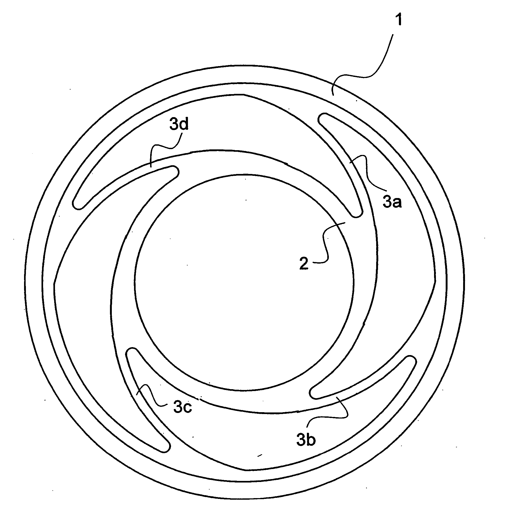
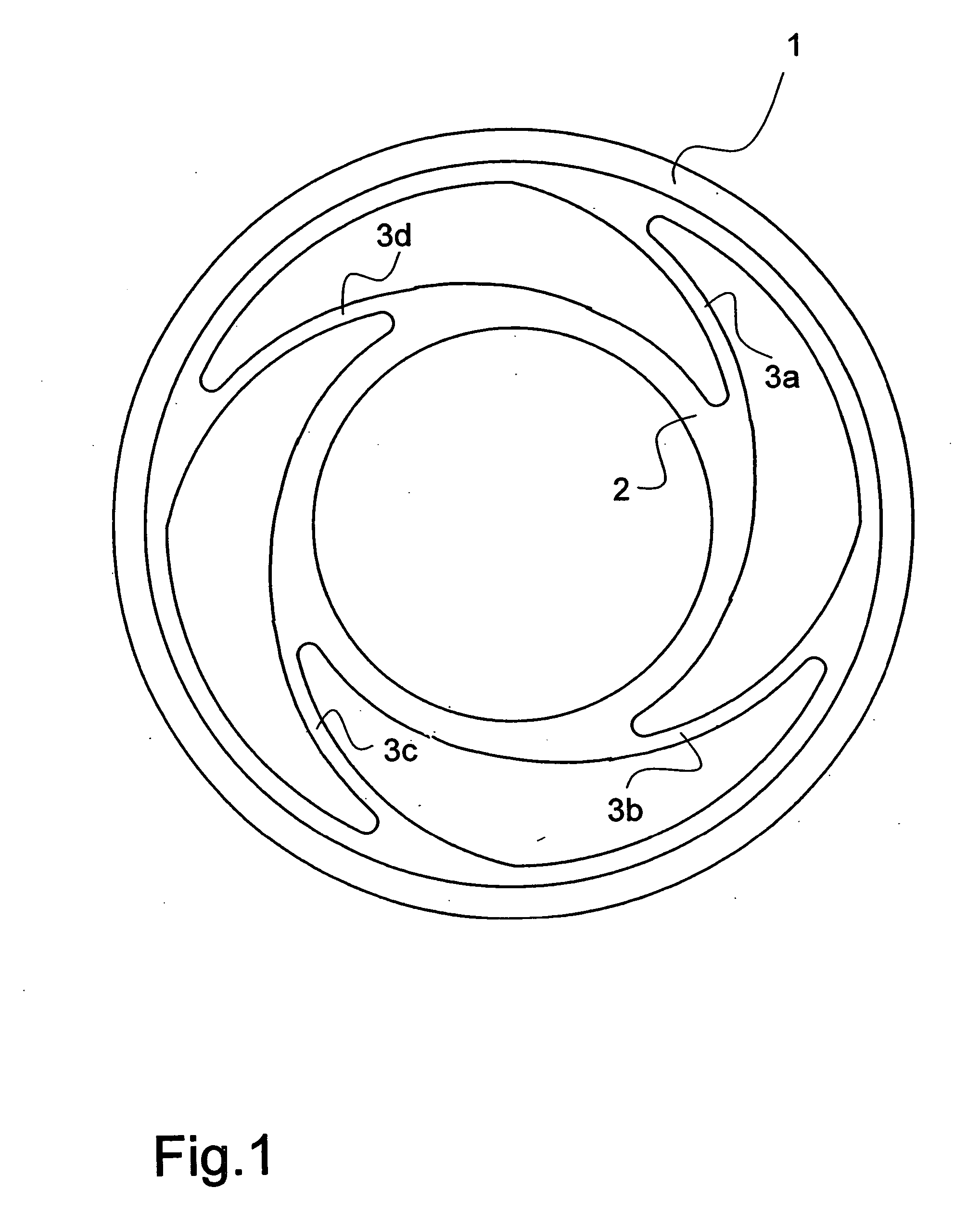
[0013] Referring now to FIG. 1 there is illustrated a basic embodiment of a compensating coupling comprising a preferably monolithic mount, an outer ring 1 and an inner ring 2 interconnected by arcuate or curved webs 3a to 3d.

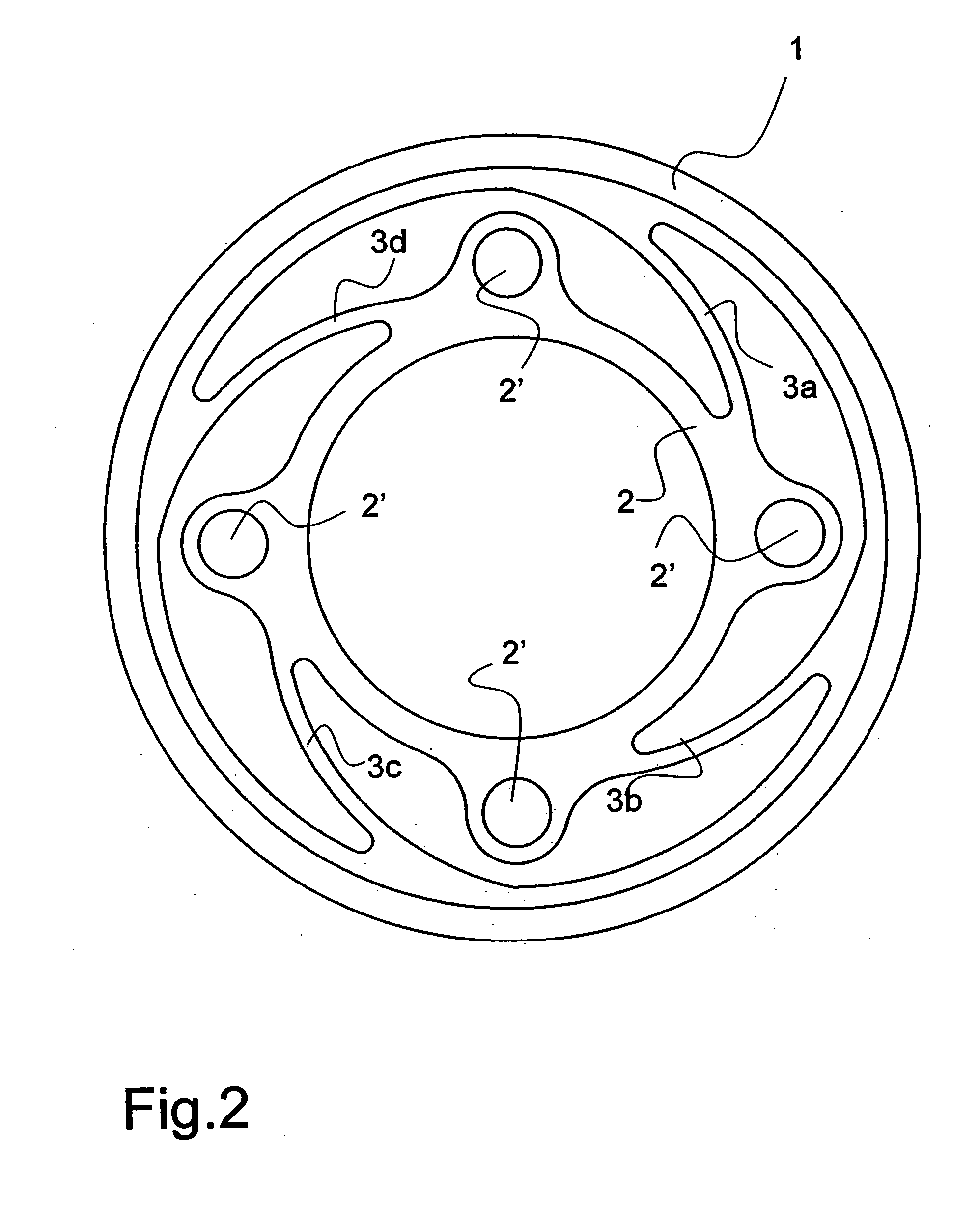
[0014] Referring now to FIG. 2 there is illustrated a modified embodiment of a compensating coupling which differs from the basic embodiment by points of force application 2′ being configured on the inner ring 2.

[0015] Referring now to FIG. 3 there is illustrated how the outer ring 1 of the compensating coupling is connected to a sheave 4 of a drive of which only part of a transmission ribbed belt 5 is indicated in FIG. 3. In FIG. 3 the inner ring 2 is connected for example to the wave generator 6 of a harmonic drive gearing.

[0016] It is because of the arcuate shape of the webs 3a to 3d that they are shortened or lengthened without being extended completely on application of a torque. The webs 3a to 3d are thus, because of the arcuate shape, subjected to substa


PUM


Abstract

For compensating axle misalignment between an input shaft or output shaft and gearing a highly compact and lightweight shaft coupling is achieved, wherein a preferably monolithic mount comprises an outer ring (1), an inner ring (2) and at least two, preferably three, arcuate connecting webs (3a to 3d) configured between outer ring and inner ring.

Description


Claims


Application Information

Patent Timeline
Owner DEUTSCHES ZENTRUM FUER LUFT & RAUMFAHRT EV
Why Eureka
Try Eureka