Automated control of razor blade colorization

Inactive Publication Date: 2007-06-14
GILLETT THE
View PDF38 Cites 12 Cited by
  • Summary
  • Abstract
  • Description
  • Claims
  • Application Information

AI Technical Summary

Problems solved by technology

If the steel is over tempered it will lose its hardness and may not perform properly during use.
The hardening process results in martenization of the blade material.
If a thermal oxide coloration process were employed after the martensitic transformation, it would generally destroy the martensitic properties of the stainless steel strip.
The hardening process results in martenization of the blade material.
If a coloration process were employed after the martensitic transformation, it would either destroy the martensitic properties of the stainless steel strip, or would require extensive temperature control and special material handling.
Constructive interference occurs when the reflected light from one interface combines in phase with the reflected light from the other interface, producing brightness.
Destructive interference occurs when the reflected light from the interfaces combines

Method used


Image

  • Automated control of razor blade colorization
  • Automated control of razor blade colorization
  • Automated control of razor blade colorization

Examples


Embodiment Construction

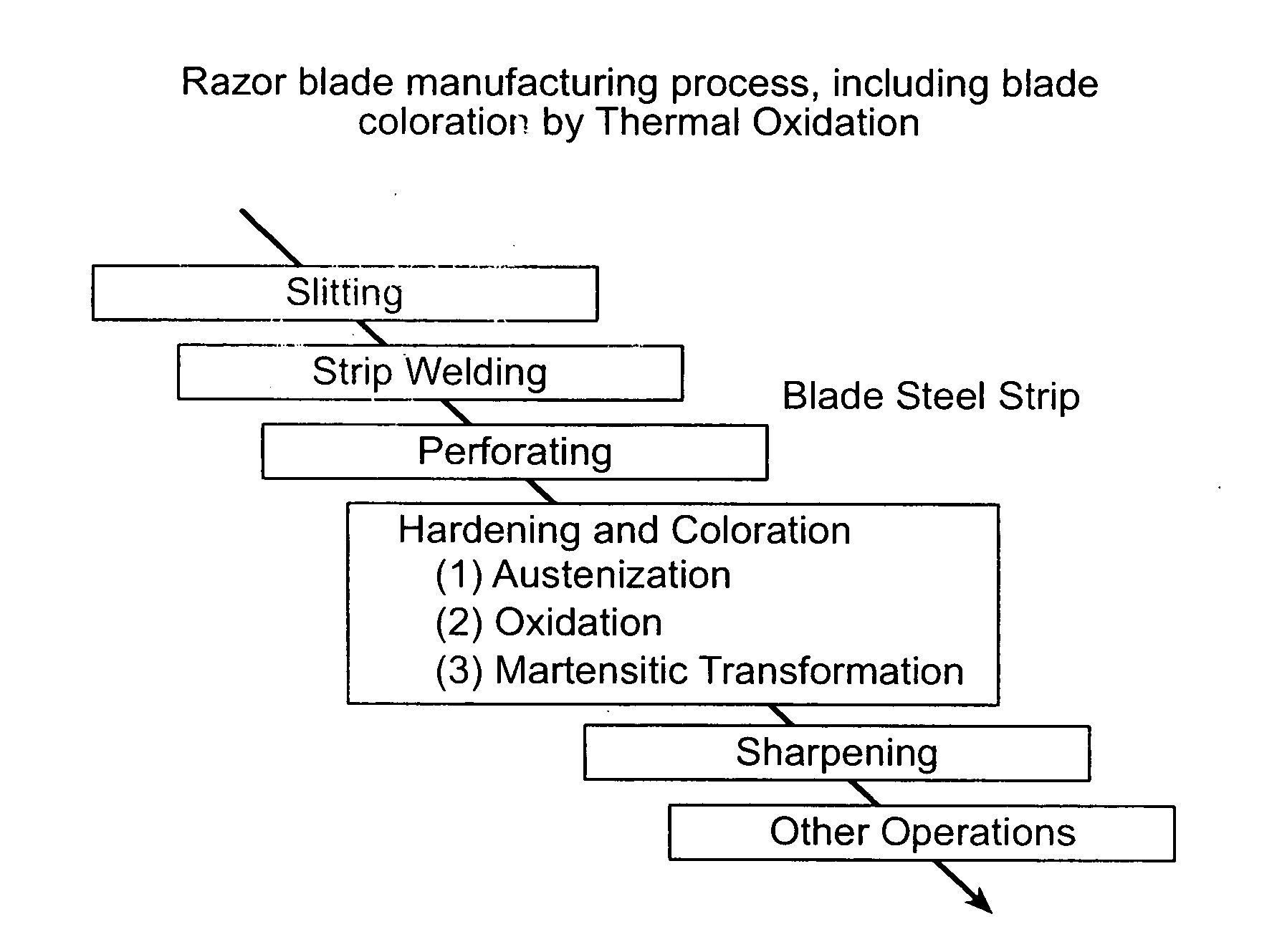
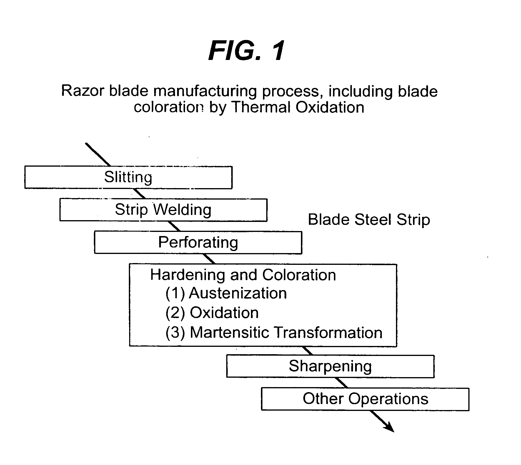
[0039] A suitable thermal oxide process for forming the colored oxide layer and manufacturing the razor blade is shown diagrammatically in FIG. 1. First, a sheet of blade steel is slit into strips. The strips are then welded together and then perforated for ease of handling during subsequent processing.

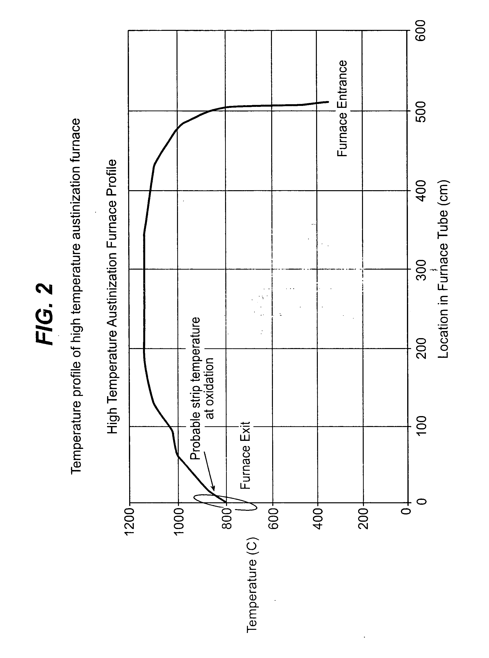
[0040] When the desired sequence of pre-hardening steps has been completed, the blade material is subjected to a hardening process, which includes austenization of the stainless steel. A typical temperature profile for the hardening process, which is conducted in a tunnel oven, is shown in FIG. 2. The material is quickly ramped up to a high temperature, e.g., approximately 1160° C., maintained at this temperature for a period of time, during which austenization of the stainless steel occurs, and then allowed to cool. A forming gas (e.g., including hydrogen and nitrogen) flows through the high temperature zone of the oven during austenization. The composition and flow rate of the forming


PUM

PropertyMeasurementUnit
Timeaaaaaaaaaa
Flow rateaaaaaaaaaa
Coloraaaaaaaaaa

Abstract

Methods of and systems for automated color control are provided. These methods and systems are suitable for use in various oxidation processes for the coloration of heat treated steel, for example razor blade steel. A feedback loop (closed loop control) is established, including the steps of measuring color, comparing the measured color to a target color and quantifying the difference there-between, and, if the difference exceeds a predetermined threshold, adjusting a color adjustment parameter, e.g., the airflow to the oxidation zone, so that the measured and target colors are equivalent or within a predetermined variance.

Description


Claims


Application Information

Patent Timeline
Owner GILLETT THE
Why Eureka
Try Eureka