Chemical Mechanical Polishing Pad

Inactive Publication Date: 2007-09-27
BAJAJ RAJEEV
View PDF38 Cites 7 Cited by
  • Summary
  • Abstract
  • Description
  • Claims
  • Application Information

AI Technical Summary

Problems solved by technology

Another aspect of existing polishing pads is that they have no ability to modulate the removal profile across the width of a wafer.
In cases of critical process modules, such as copp

Method used


Image

  • Chemical Mechanical Polishing Pad
  • Chemical Mechanical Polishing Pad

Examples


Embodiment Construction

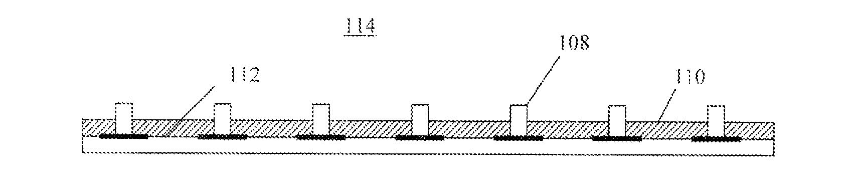
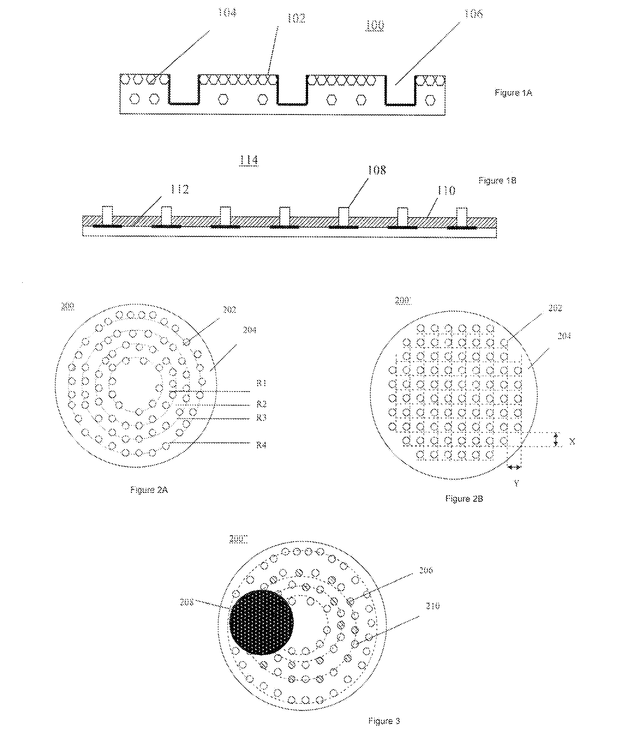
[0016]Described herein is a CMP polishing pad which allows for establishing a predefined, non-planar material removal profile. In one embodiment, the pad includes polishing elements, which are placed on an underlying compressible foam and protrude through holes in a guide plate overlaid on that foam. The nominal size of each polishing element is 0.25 inches and the height thereof is 0.160 inches. The compressible foam is nominally 0.060″ thick.

[0017]Note that although the present polishing pad is discussed with reference to certain illustrated embodiments, the scope of the present invention is not intended to be limited thereby. Instead, the present invention should only be measured in terms of the claims, which follow this description.

[0018]The present pad design enables the application very uniform pressure onto a wafer and eliminates (or at least substantially reduces) edge effect typically associated with full sheet polishing pads. This translates to a very uniform material removal


PUM


Abstract

A polishing pad has polishing elements of at least two different types of materials, each having a different coefficient of friction, and arranged over a surface of the pad so as to provide a non-planar material removal profile for the pad. The polishing elements may be arranged to provide different material removal profiles, such as an edge-fast, edge-slow, center-fast or center-slow material removal profile.

Description


Claims


Application Information

Patent Timeline
Owner BAJAJ RAJEEV
Why Eureka
Try Eureka