Charging roller and image forming apparatus incorporating same
a charging roller and image forming technology, applied in the direction of electrographic process apparatus, instruments, corona discharge, etc., can solve the problems of difficult reliable prevention, high current leakage, and often partial loss of processing effect, and achieve stable conduction
- Summary
- Abstract
- Description
- Claims
- Application Information
AI Technical Summary
Benefits of technology
Problems solved by technology
Method used
Image

Examples
embodiments
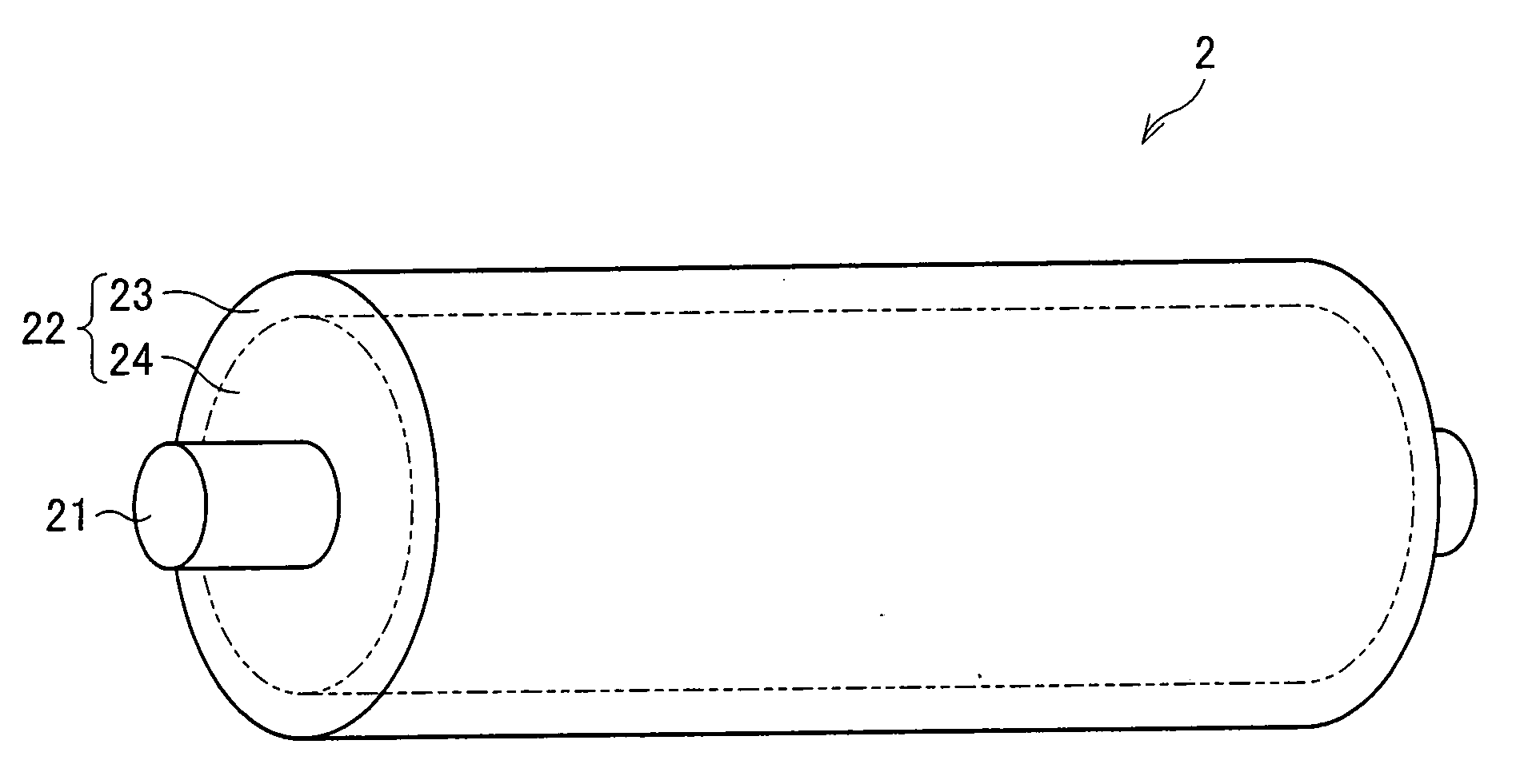
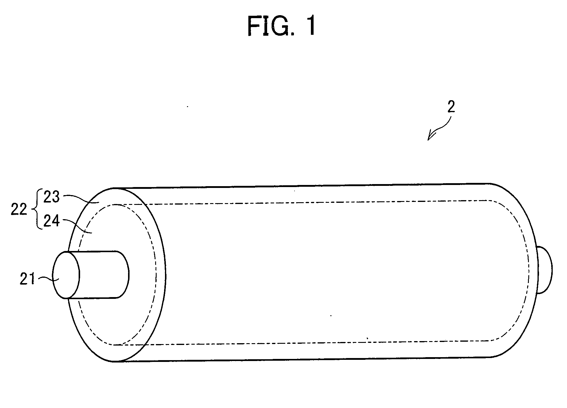
[0024]The following will describe an embodiment of the present invention in reference to FIGS. 1 to 4.
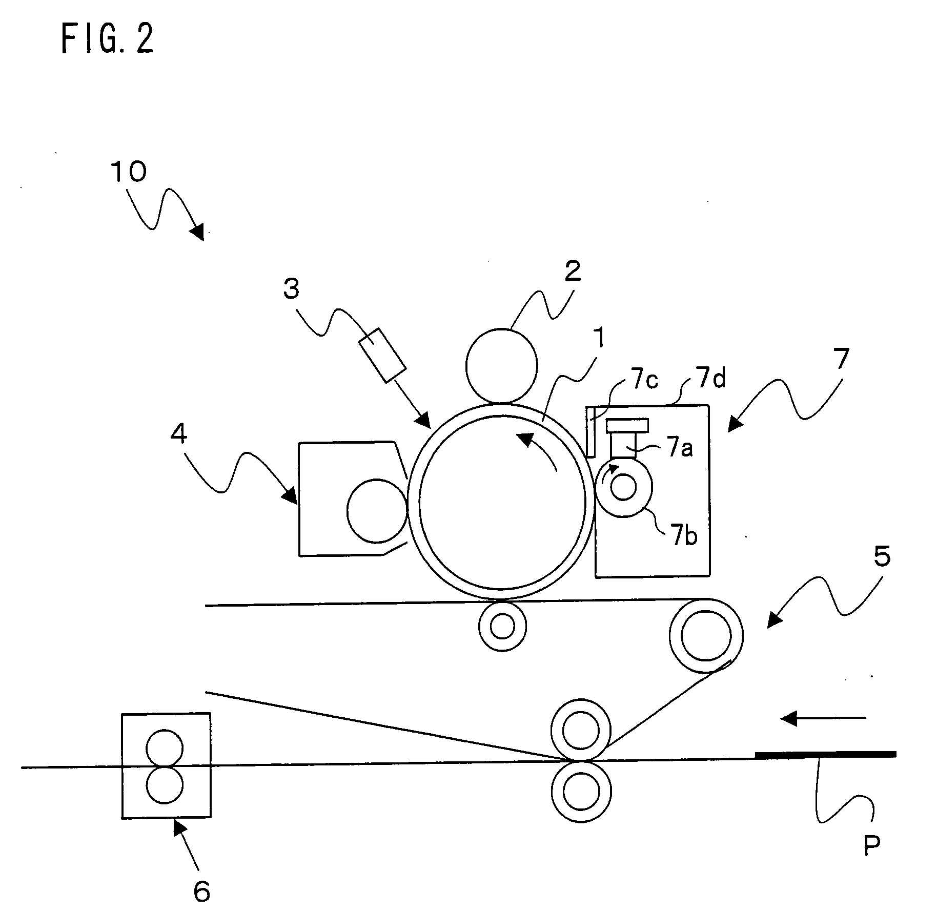
[0025]Referring to FIG. 2, the structure of major features of an image forming apparatus 10 of the present embodiment will be described. FIG. 2 is a vertical cross-sectional view of the image forming apparatus 10 when viewed from the front.
[0026]As shown in FIG. 2, the image forming apparatus 10 forms an image represented by image data on a sheet of paper by an electrophotographic scheme. The image forming apparatus 10 contains a photoreceptor (image carrier) 1. Around the photoreceptor 1 are there provided components which perform a well-known Carlson process: namely, a charging roller 2, illumination unit 3, developing unit 4, transfer unit 5, fusing unit 6, and cleaning unit 7.
[0027]The photoreceptor 1 is shaped like a drum and supported at its axis by a housing (not shown) in such a way that it is rotatable. The photoreceptor 1 contains a support body having a photosensitive layer
example 1
[0073]The electronic conductive agent was added in a less amount in the present example than in comparative example 1. The resultant pseudo charging roller 12, containing only the electronic conductive agent, had a resistance of 105.5Ω and a volume resistivity of 1.46×10⁶ Ω·cm (see Table 1 below).
[0074]Next, another pseudo charging roller 12 was fabricated which contained the aforementioned amount of the electronic conductive agent and a predetermined amount of the ionic conductive agent. The resistance and volume resistivity of the pseudo charging roller 12 were calculated to be 105.4Ω and 1.16×10⁶ Ω·cm respectively (see Table 1 below).
[0075]It was examined, similarly to comparative example 3, whether or not there occurred current leakage to the photoreceptor 1 from this pseudo charging roller 12 containing the electronic conductive agent and the ionic conductive agent, but not having been subjected to surface processing. The examination was performed with the lubricant being applied
example 2
[0077]The electronic conductive agent was added in an even less amount in the present example than in example 1. The resultant pseudo charging roller 12, containing only the electronic conductive agent, had a resistance of 105.6Ω and a volume resistivity of 1.84×10⁶ Ω·cm (see Table 1 below).
[0078]Next, another pseudo charging roller 12 was fabricated which contained the aforementioned amount of the electronic conductive agent and a predetermined amount of the ionic conductive agent. The resistance and volume resistivity of the pseudo charging roller 12 were calculated to be 105.48Ω and 1.40×10⁶ Ω·cm respectively (see Table 1 below).
[0079]It was examined, similarly to comparative example 3, whether or not there occurred current leakage to the photoreceptor 1 from this pseudo charging roller 12 containing the electronic conductive agent and the ionic conductive agent, but not having been subjected to surface processing. The examination was performed with the lubricant being applied to th
PUM
 Abstract
Description
Claims
Application Information
 - R&D Engineer
- R&D Manager
- IP Professional
- Industry Leading Data Capabilities
- Powerful AI technology
- Patent DNA Extraction
Browse by: Latest US Patents, China's latest patents, Technical Efficacy Thesaurus, Application Domain, Technology Topic.
© 2024 PatSnap. All rights reserved.Legal|Privacy policy|Modern Slavery Act Transparency Statement|Sitemap