System and method for photo/art frame eternal depth illusion

Inactive Publication Date: 2007-11-08
DRIESSEN JAMES LEONARD
View PDF2 Cites 4 Cited by
  • Summary
  • Abstract
  • Description
  • Claims
  • Application Information

AI Technical Summary

Benefits of technology

[0012]When the mirrors are in this position we say that they are diametrically positioned meaning that the reflective portions of the mirrors are at least in some respect facing each other. Diametrical should not be taken to mean that the mirrors must be exactly parallel or facing each other exactly because we know that no two planes are exactly parallel. But, we also do not mean that the two mirrors have to be precisely diamet

Problems solved by technology

It is practically impossible to keep the camera out of the picture, especially, if shot st

Method used


Image

  • System and method for photo/art frame eternal depth illusion
  • System and method for photo/art frame eternal depth illusion
  • System and method for photo/art frame eternal depth illusion

Examples


Embodiment Construction

[0021]In the preferred embodiment of this invention, the elements of the System and Method for Photo / Art Frame Eternal Depth illusion are kept most simple. It is important for the reader of this patent application to know, however, that simplicity is not a bar to patentability. Thus, depicting the preferred embodiment of the present invention using the most simple forms, terms, and illustrations will best allow the reader to quickly grasp the novelty and usefulness of this invention, but this simplicity is not to be taken to mean that the inventor in any way limits the embodiments of this invention to only the most simple: many complex embodiments which can be derived from the lessons taught in this application may be employed.

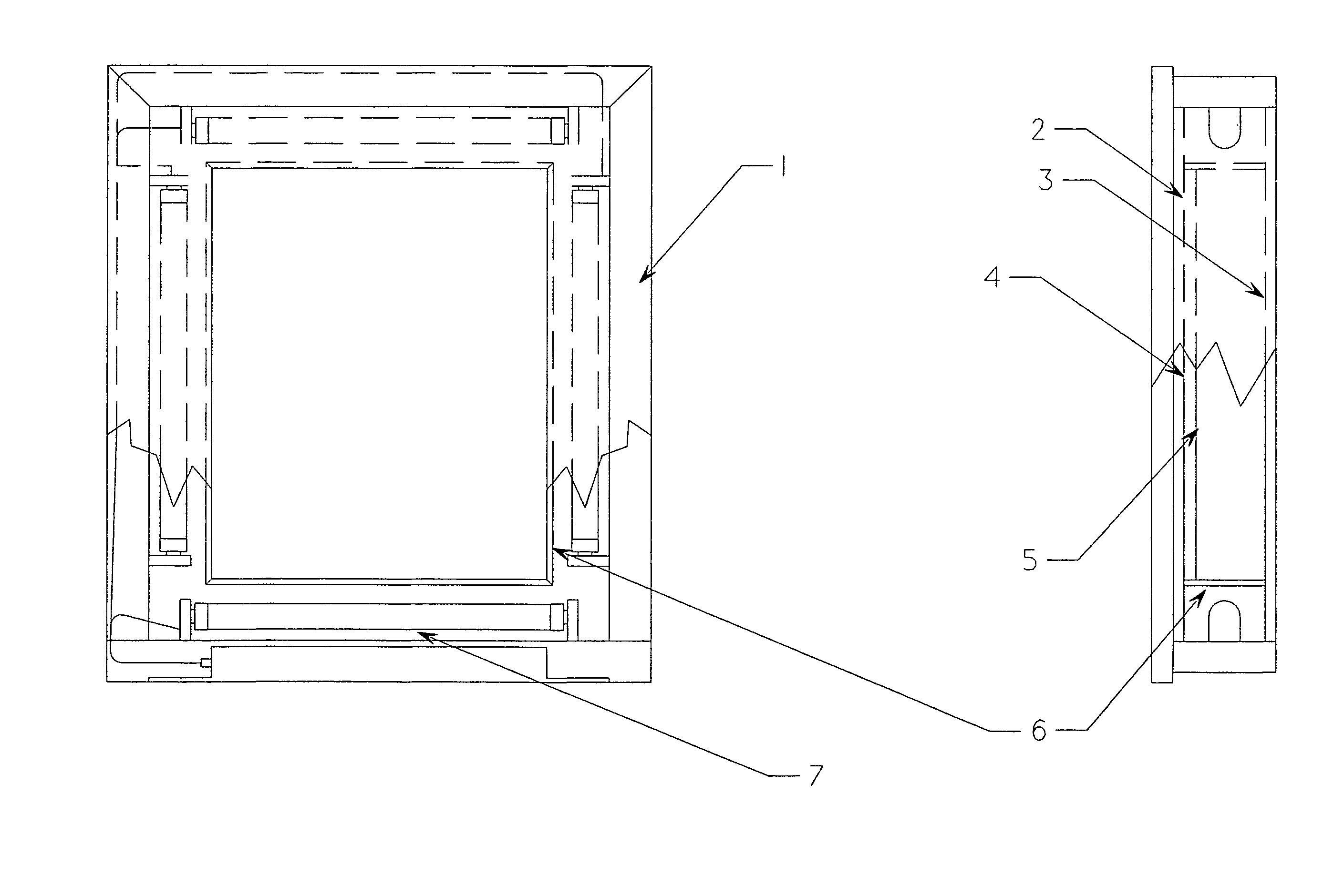
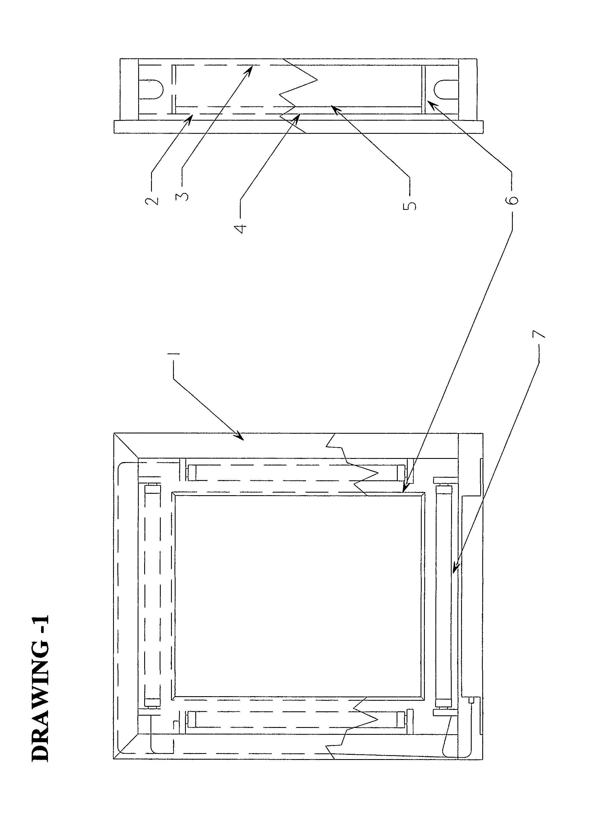
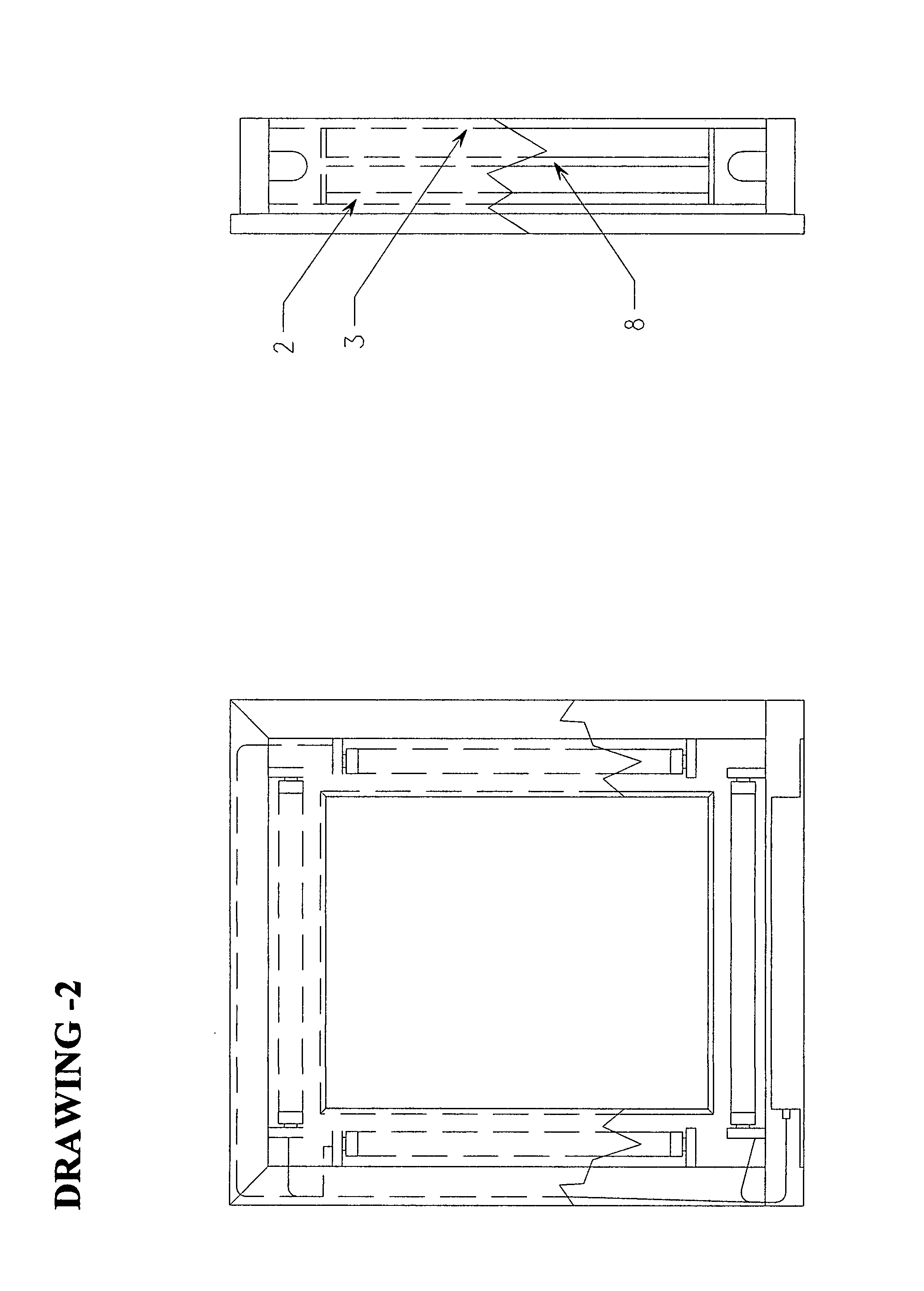
[0022]In practice, the System and Method for Photo / Art Frame Eternal Depth illusion must create the eternal depth illusion without bringing exterior elements into the art frame, meaning we want to be able to both view the photo or art work in the frame with a


PUM


Abstract

Hand engraved etchings, computer generated sandblastings, transparencies, or any other photo or art work may be precisely and deliberately placed within the interior of a lighted “shadow box” fine art frame. Those photo and art works are then either directly or indirectly applied onto or used in conjunction with glass, acrylic, or other framing components, to create a plurality of lights, glass, half-silvered glass, and mirrors within the photo/art frame housing. The framing components secure the glass and mirrors in various diametrically situated positions as to cause an illusion of eternal reflection of not only the lighting elements, but also of the art work. The Photo/Art Frame Eternal Depth Illusion invention brings together the worlds of photo and art framing together with the infinity lighting concept. This system and method allows for the light and artwork to be reflected seemingly endlessly and to create a seemingly eternal depth illusion for a work of art or photo to be used in many different applications.

Description


Claims


Application Information

Patent Timeline
Owner DRIESSEN JAMES LEONARD
Why Eureka
Try Eureka