Method and Apparatus for Reducing Jitter in Multi-Gigahertz Systems

a multi-gigahertz system and jitter reduction technology, applied in the field of signal processing systems, can solve the problems of large jitter reduction difficulty in current systems, high jitter in random jitter (rj) and other problems, and achieve the effect of low jitter and less jitter

Inactive Publication Date: 2008-10-16
GEORGIA TECH RES CORP +1
View PDF21 Cites 4 Cited by
  • Summary
  • Abstract
  • Description
  • Claims
  • Application Information

AI Technical Summary

Benefits of technology

This patented technology solves problems caused by electrical signals being distorted due to external factors like temperature or power supply changes over time. By adjusting certain parameters on both the input sources (the primary) and the secondary(s), it can generate similar but slightly different outputs based upon these variations. Additionally, this technique allows multiple generations of identical devices to be produced without any issues associated therewith.

Problems solved by technology

Technological Problem: High Frequency Electronic Instruments (HFESI) face difficulties controlling interference caused by random noise during measurements due to their small size. Current solutions involve adding extra hardware or modifying software settings but they require significant resources and result in increased cost. There is also a challenge related to maintaining precise synchronization across multiple devices without increasing complexity beyond what was previously necessary.

Method used


Image

  • Method and Apparatus for Reducing Jitter in Multi-Gigahertz Systems
  • Method and Apparatus for Reducing Jitter in Multi-Gigahertz Systems
  • Method and Apparatus for Reducing Jitter in Multi-Gigahertz Systems

Examples


experimental embodiment

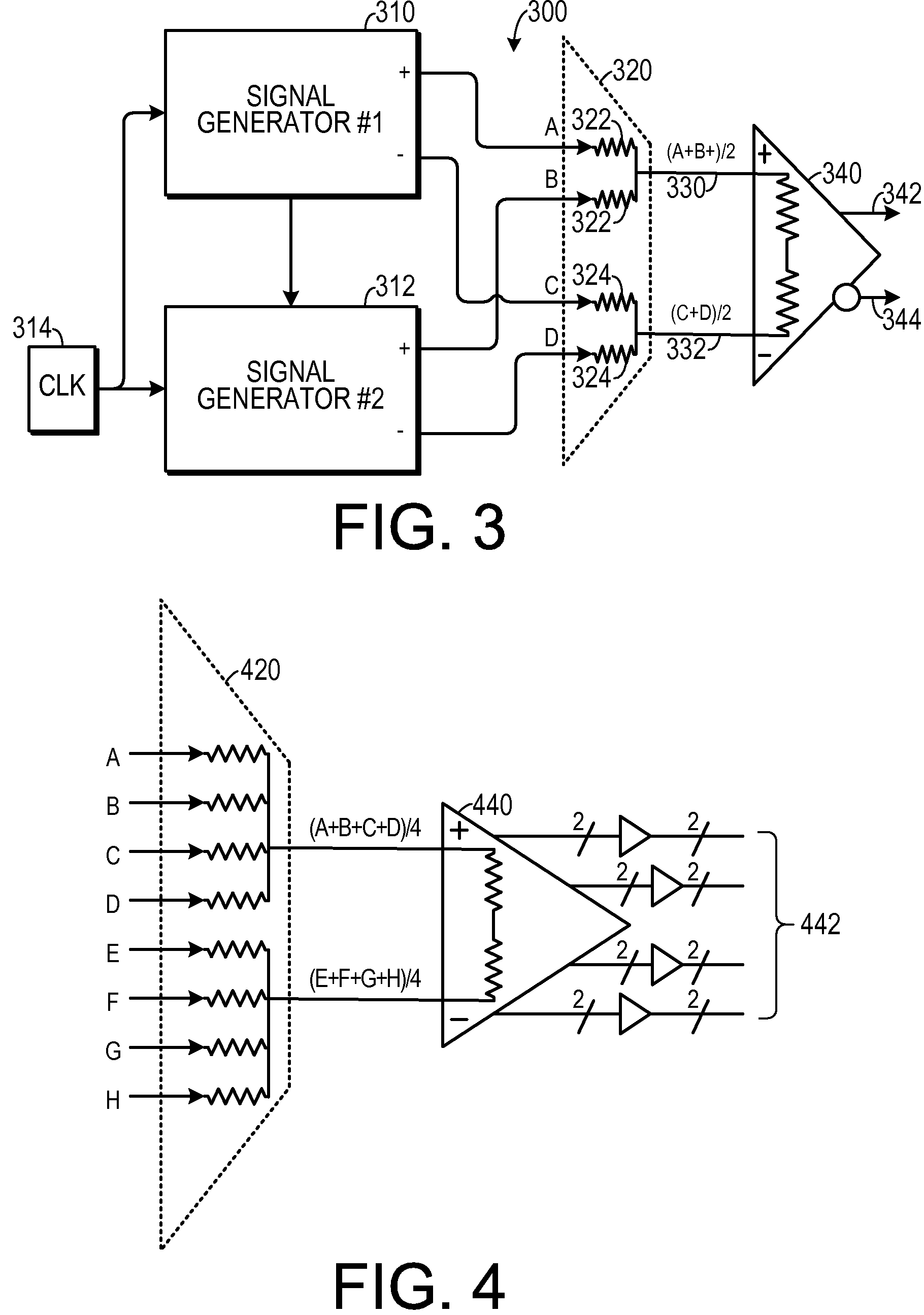
[0028]One experimental embodiment and supporting theory is now disclosed. Because testing at multi-gigahertz frequencies is so dependent on high-accuracy timing signals, it may be necessary to utilize more automated test equipment (“ATE”) resources for the most critical signals (such as clocks and timing references). In one experimental embodiment, multiplexing and demultiplexing modules were added to loadboards to synthesize multi-gigahertz test patterns using multiple 1 Gbps ATE channels.

[0029]Several “Driver” and “Receiver” modules were used to provide over 80 multi-Gbps differential channels in a combination of HyperTransport (1.6 Gbps per channel) and PCI-express (at 2.5 Gbps per channel). The ATE jitter level was typically in the range of 4 ps-8 ps, which is not sufficiently low for our testing needs in the 3 to 10 Gbps range. Therefore, a low-jitter (˜1.4 ps) RF clock source was used to provide a programmable timing reference to each of the modules. This level of jitter is a fac


PUM


Abstract

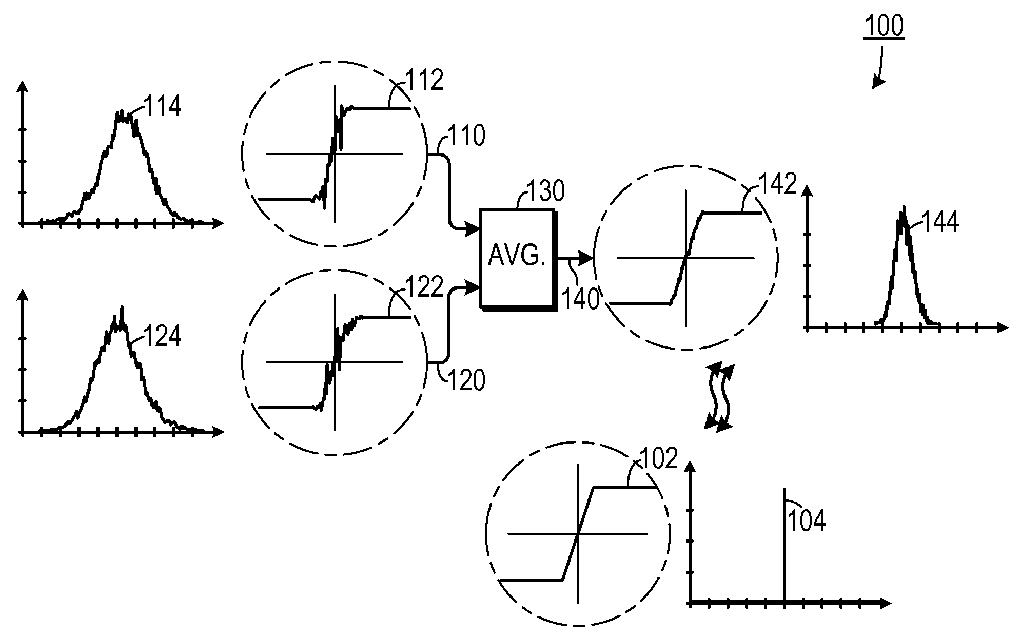
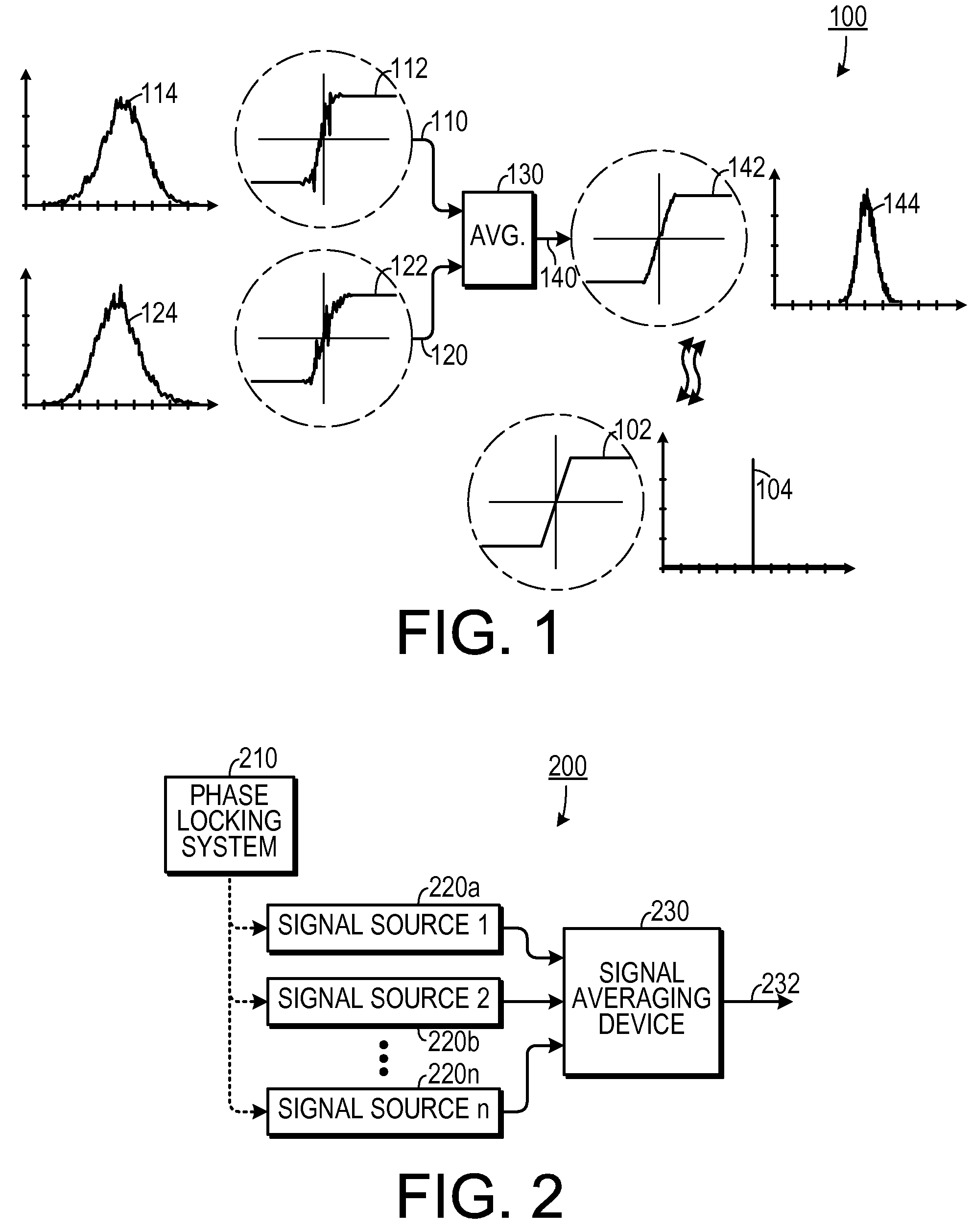
An apparatus for generating an output signal that is analogous to an first signal from a first signal source that exhibits a first jitter, so that the output signal exhibits less jitter than the first jitter includes at least one second signal source generates a second signal that is analogous to and phase locked with the first signal. The second signal exhibits a second jitter that is uncorrelated with the first jitter. A signal averaging device is responsive to the first signal and the second signal. The signal averaging device averages the first signal and the second signal with respect to at least one parameter and thereby generates the output signal.

Description


Claims


Application Information

Patent Timeline
Owner GEORGIA TECH RES CORP
Why Eureka
Try Eureka