Securing device for a power supply adapter

a technology for securing devices and power supply adapters, which is applied in the direction of coupling devices, two-part coupling devices, electrical apparatus, etc., can solve the problems of no locking mechanism for the combination to secure the plug on the body, and difficulty in using electrical appliances

Inactive Publication Date: 2008-10-30
DIGITONE INDAL
View PDF3 Cites 1 Cited by
  • Summary
  • Abstract
  • Description
  • Claims
  • Application Information

AI Technical Summary

Benefits of technology

The purpose of this invention is to provide an improved securing device used with plugs or pipes. It consists of a tapered part at one end of the plug that fits into a corresponding hole in the cap. When two tubes are connected together, they rotate within the holes until it matches up properly. This ensures that the plug stays fixedly attached to the pipe.

Problems solved by technology

This patent describes a problem with current power supply adapters used by businesses who require both flat and circular sockets. These adapters are designed to connect to standard sockets but there can also be issues with the plug falling out or causing fires if needed. To address these concerns, an improved securing device is described.

Method used


Image

  • Securing device for a power supply adapter
  • Securing device for a power supply adapter
  • Securing device for a power supply adapter

Examples


Embodiment Construction

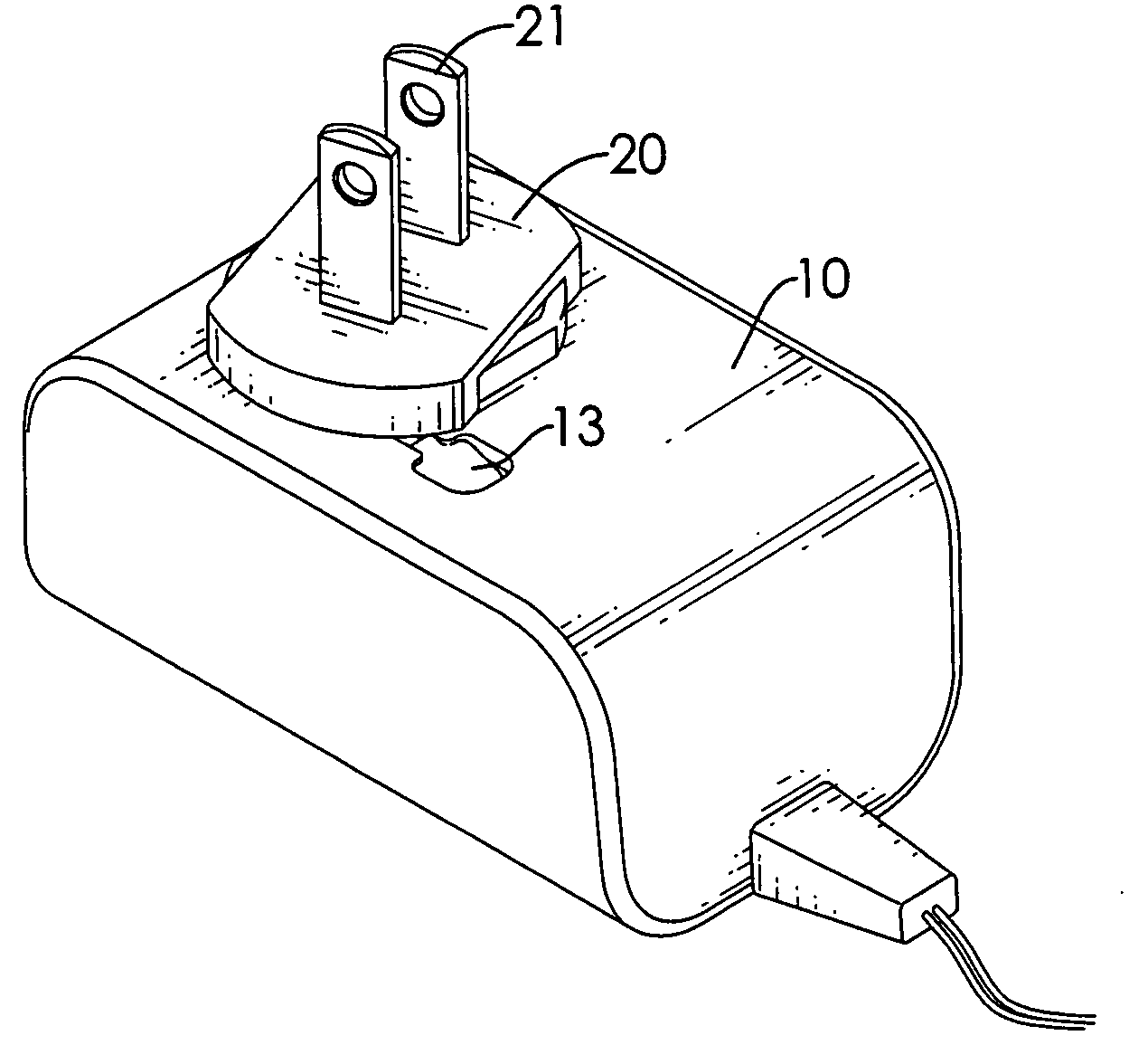
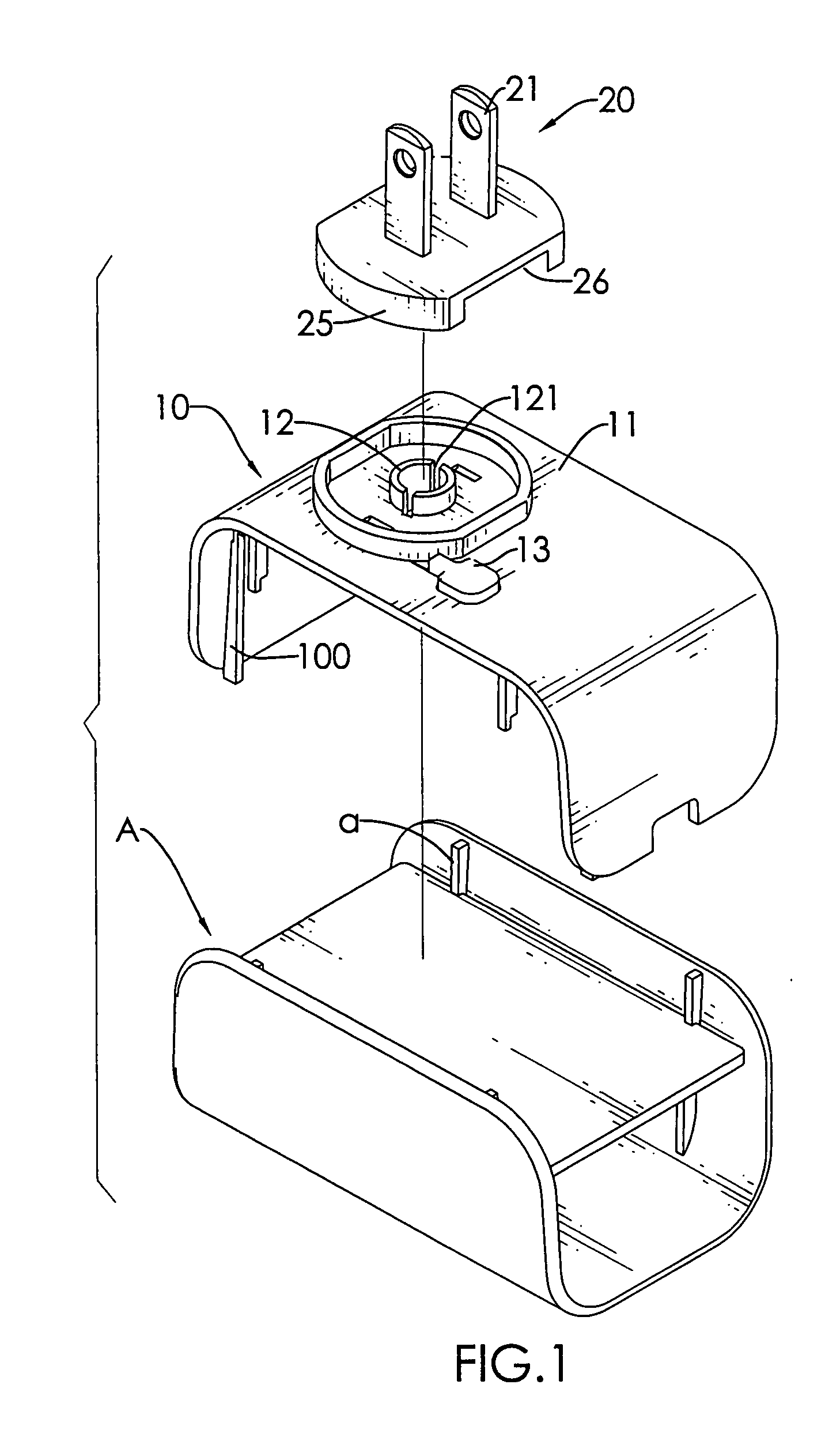
[0020]With reference to FIGS. 1 and 2, it is noted that a power supply adapter of the present invention includes a body (A), a cap (10) and a plug (20). The body (A) has two upright walls oppositely opposed to each other and each upright wall has multiple ribs (a) formed on an inner face of the upright wall. The cap (10) is substantially U shaped and has multiple sliding tracks (100) formed on an inner face of the cap (10) to correspond to the ribs (a) of the body (A). Therefore, the cap (10) is able to slidably connect to the body (A) with the ribs (a) received in the corresponding sliding tracks (100). However, the combination between the cap (10) and the body (A) is not the focus of the present invention. The focus lies on the structure to secure the plug (20) on top of the cap (10) after the cap (10) is secured to the body (A).

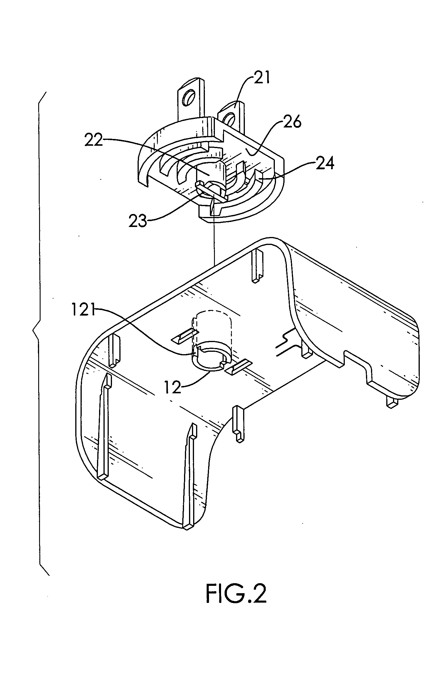
[0021]In order to accomplish the objective of securing the position of the plug (20) on top of the cap (10), the cap (10) is provided with a protruded ring (


PUM


Abstract

A securing device for a power supply adapter includes a first tube extending through a cap and having a cutout defined in two opposed sides of the first tube and a second tube extending from a bottom face of a plug to be rotatably received in and extended out of the first tube and having a stop axially formed on a free end of the second tube to correspond to and be received in the cutout when the second tube is received in the first tube and the stop abuts a bottom peripheral edge of the first tube when the second tube is rotated relative to the first tube such that engagement between the plug and the cap is secured.

Description


Claims


Application Information

Patent Timeline
Owner DIGITONE INDAL
Why Eureka
Try Eureka