Communication control method, receiving station apparatus, transmitting station apparatus, and communication system
a communication control and receiving station technology, applied in the direction of transmission path division, transmission monitoring, line-transmission details, etc., can solve the problems of increasing the overhead of the guard interval, deteriorating the characteristic, and deteriorating the character, and achieve excellent communication quality
- Summary
- Abstract
- Description
- Claims
- Application Information
AI Technical Summary
Benefits of technology
Problems solved by technology
Method used
Image

Examples
first embodiment
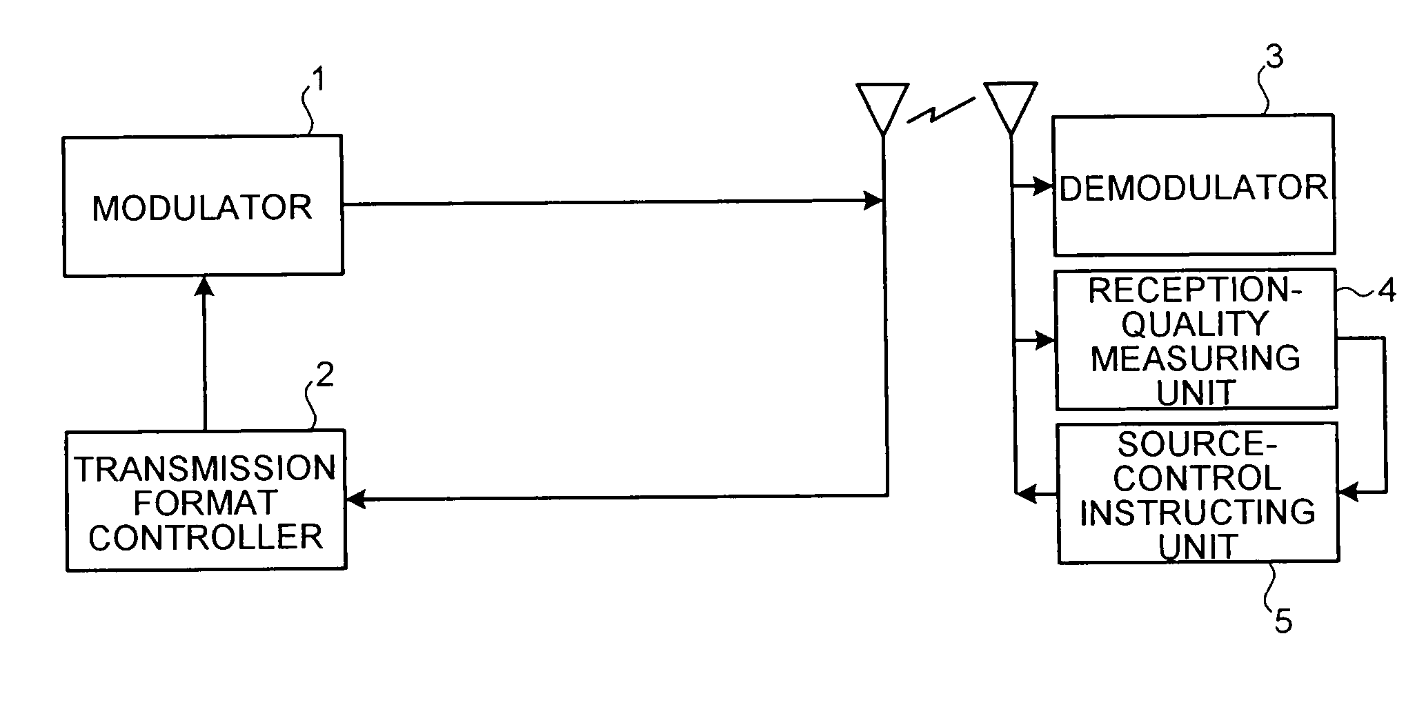
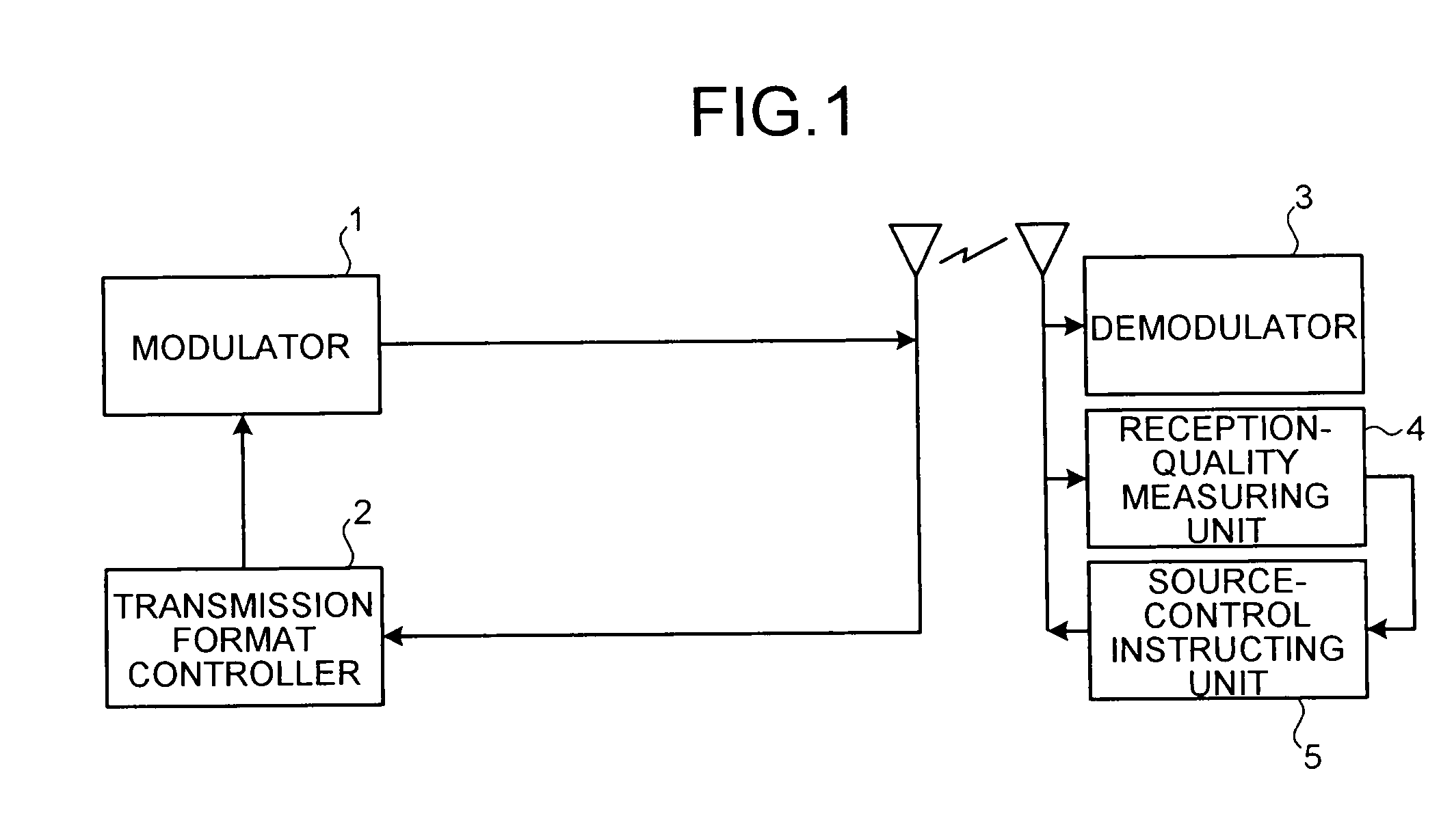
[0086]FIG. 1 is a configuration example of a communication system that realizes a communication control method according to a first embodiment, and is a configuration example of an OFDM system that performs one-to-one two-way communication. The communication system includes a transmitting station apparatus (hereinafter, “transmitting station”) including a modulator 1 and a transmission format controller 2, and a receiving station apparatus (hereinafter, “receiving station”) including a demodulator 3, a reception-quality measuring unit 4, and a source-control instructing unit 5. Although not shown, the transmitting station and the receiving station include a module for performing a transmission process and a reception process for performing a transfer process of a signal, and transfer a user signal (data), a source-control instructing signal, a reception quality signal, or the like described later. This applies to the transmitting station and the receiving station in the following embod
second embodiment
[0100]A second embodiment is explained next. FIG. 5 is a configuration example of the communication system according to the second embodiment, and is a configuration example of the OFDM system that performs the one-to-one two-way communication as in the first embodiment. The transmitting station of the communication system includes the modulator 1 and the transmission format controller 2, and further includes the source-control instructing unit 5, which is included in the receiving station of the communication system according to the first embodiment. On the other hand, the receiving station includes only the demodulator 3 and the reception-quality measuring unit 4. The source-control instructing unit 5 operates as a number-of-null carriers determining unit in claim 18.
[0101]In the communication system of the present embodiment, the receiving station transmits the reception quality measurement result of the signal measured by the reception-quality measuring unit 4 to the transmitting s
third embodiment
[0104]A third embodiment is explained next. FIG. 6 is a configuration example of the communication system according to the third embodiment, and is a configuration example of the OFDM system that performs the one-to-one two-way communication as in the first embodiment. The transmitting station in the communication system includes the modulator 1, the transmission format controller 2, and the source-control instructing unit 5 included in the receiving station in the communication system of the first embodiment, and further includes a destination-quality estimating unit 7 that operates as a reception-quality estimating unit in claim 20. On the other hand, the receiving station includes the demodulator 3 and a quality-estimating signal generator 6. The source-control instructing unit 5 operates as a number-of-null carriers determining unit in claim 20.
[0105]In the communication system of the present embodiment, the transmitting station estimates the reception quality of the signal in the
PUM
 Abstract
Description
Claims
Application Information
 - R&D Engineer
- R&D Manager
- IP Professional
- Industry Leading Data Capabilities
- Powerful AI technology
- Patent DNA Extraction
Browse by: Latest US Patents, China's latest patents, Technical Efficacy Thesaurus, Application Domain, Technology Topic.
© 2024 PatSnap. All rights reserved.Legal|Privacy policy|Modern Slavery Act Transparency Statement|Sitemap