Tire bead separation method and device

a technology of tire bead and separation method, which is applied in the field of tire building machinery, can solve the problems of damage to the assembly, extreme difficulty in separating the assembly from one another,

Inactive Publication Date: 2009-04-09
THE GOODYEAR TIRE & RUBBER CO
View PDF14 Cites 3 Cited by
  • Summary
  • Abstract
  • Description
  • Claims
  • Application Information

AI Technical Summary

Benefits of technology

The invention relates to a structure for vehicles that includes multiple layers made up from different materials called Radial Plane Structures (RPS). These structures are designed by aligning certain parts along their diagonal directions - usually six degrees apart – instead of just two angles. This design allows some material inside each layer to be used effectively without being overlooked during manufacturing processes while still maintaining strength when installed on new cars.

Problems solved by technology

This patented describes how different types of materials can stick out when used with certain parts of a vehicle's wheel during its production process due to factors like temperature changes over time (temperature fluctuations). These issues make separation between these components challenging for workers who work on their own equipment.

Method used


Image

  • Tire bead separation method and device
  • Tire bead separation method and device
  • Tire bead separation method and device

Examples


Embodiment Construction

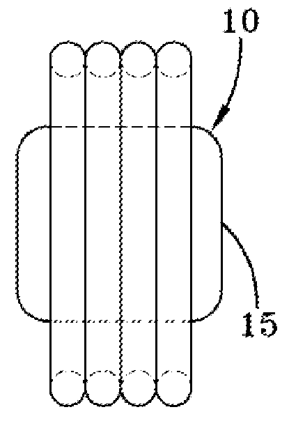
[0026]FIG. 3 illustrates a first embodiment of a separator apparatus 10 of the invention. The bead separator 10 may be used to separate stacked annular components such as annular beads, annular bead and apex assemblies or other stacked components which may or may not be circular in cross-section. The invention is thus not limited to these bead assemblies, and may be utilized to separate other annular components as well, including those annular components unrelated to tire building. The separator apparatus 10 comprises an expansion chamber 15 which may typically be circular in cross-section or any other desired cross-sectional shape which mates with the components to be separated. The expansion chamber 15 may be comprised of rubber or other expandable material. The expansion chamber 15 initially has a smaller diameter than the inner diameter of the beads or other annular component to be separated. The expansion chamber is inserted through the inner diameter of the components to be separ


PUM

PropertyMeasurementUnit
Diameteraaaaaaaaaa
Flexibilityaaaaaaaaaa

Abstract

A method and apparatus is provided for separating two or more annular members such as bead assemblies or bead and apex assemblies. First, a flexible member is inserted into the annulus of the annular members. Next, the flexible member is inflated until the outer surface of the flexible member contacts the inner diameter of the annular member. Then the flexible member is axially expanded until the annular members are separated. Then the flexible member is deflated so that the annular members can be removed.

Description


Claims


Application Information

Patent Timeline
Owner THE GOODYEAR TIRE & RUBBER CO
Why Eureka
Try Eureka