Low frequency antenna

Inactive Publication Date: 2009-04-16
ETHERTRONICS
View PDF5 Cites 5 Cited by
  • Summary
  • Abstract
  • Description
  • Claims
  • Application Information

AI Technical Summary

Benefits of technology

[0012]In another aspect, the invention relates to a communication device. The communication device includes a printed circuit board and a

Problems solved by technology

Such sizes can be inefficient and impractical for in many applications, such

Method used


Image

  • Low frequency antenna
  • Low frequency antenna
  • Low frequency antenna

Examples


Embodiment Construction

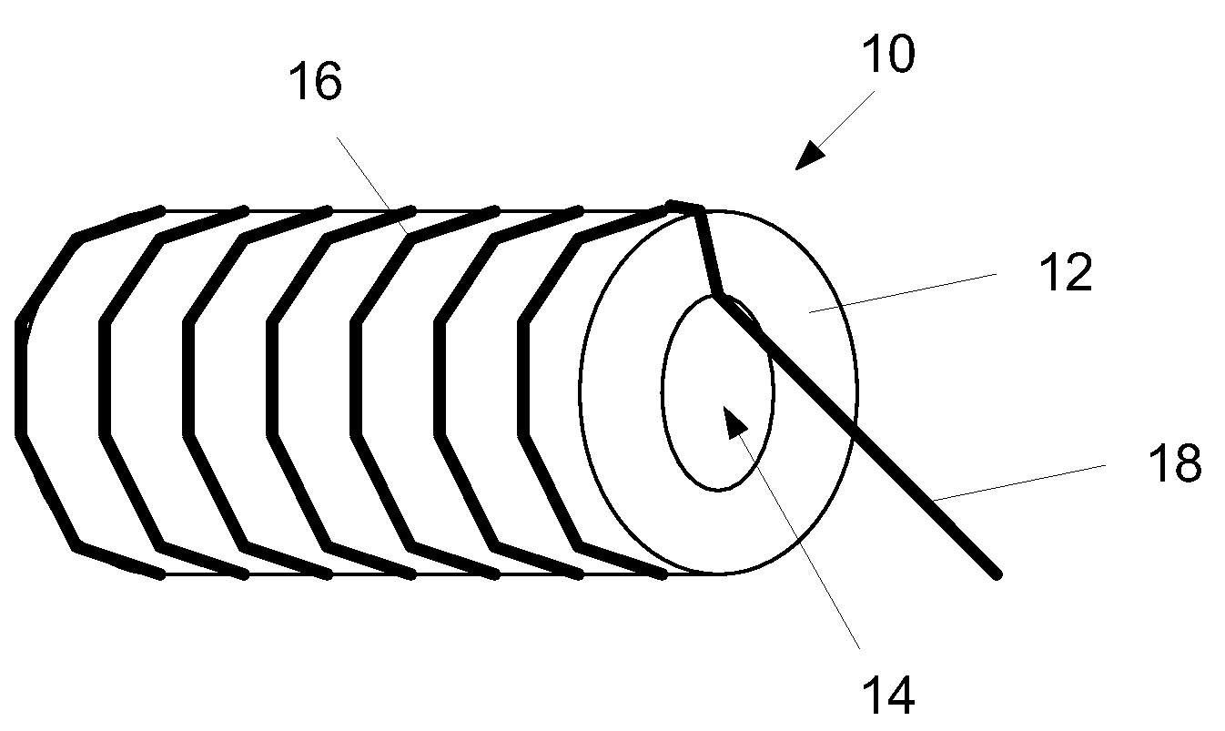
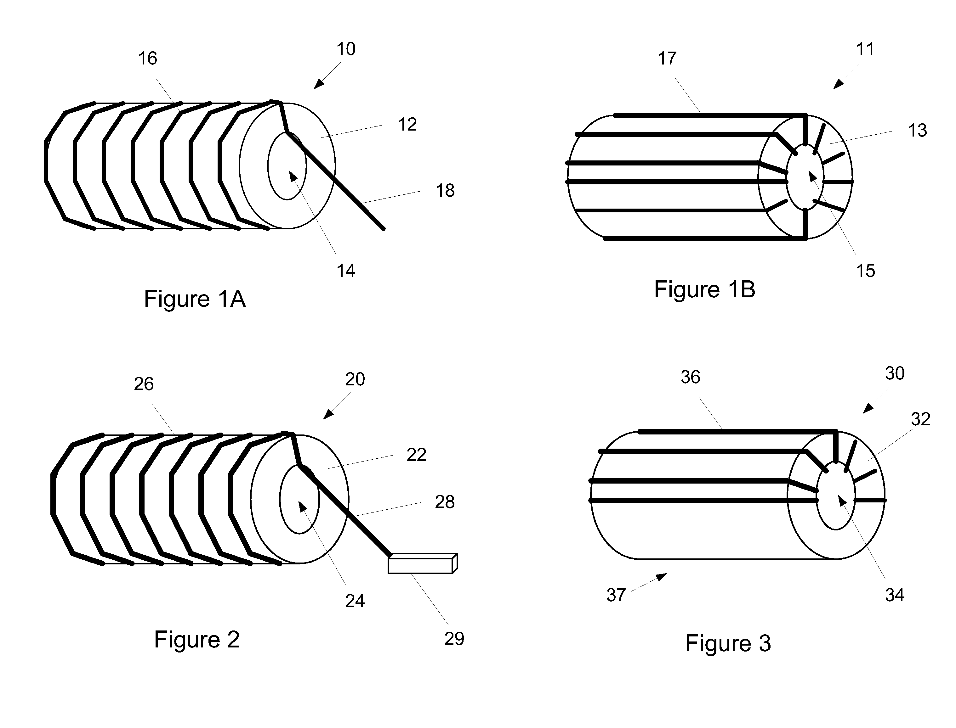
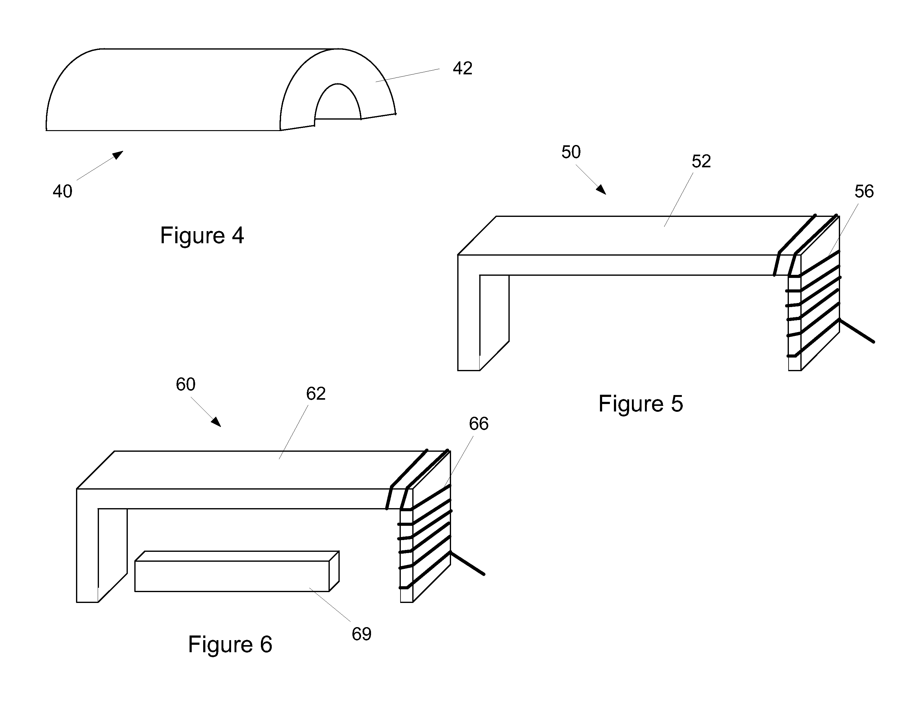
[0023]Rather than forming an antenna by wrapping a coil around a ceramic core, embodiments of the present invention reduce the size of such antennas by modifying certain material properties of the core. Specifically, in accordance with embodiments of the present invention, the permeability of the core is varied to achieve the desired result. By changing the permeability of the core, antenna parameters such as bandwidth and efficiency can be optimized or improved as the overall size is reduced.

[0024]The electromagnetic properties of materials, such as permeability and permittivity, can be understood by examination of propagation of waves. The wavelength of a wave propagating in through a material may change compared to free space propagation. In free space, the wavelength and frequency of a wave are related by:

c=fλ  (1)

[0025]where: c=speed of light (meters / second),

[0026]f=frequency in Hertz (1 / second), and

[0027]λ=wavelength (meters).

[0028]The following equation (derived directly fro


PUM


Abstract

An antenna includes a core formed of a high-permeability material and a coil wire wrapped around at least a part of the core. In one embodiment, the high-permeability material includes ferrite material.

Description


Claims


Application Information

Patent Timeline
Owner ETHERTRONICS
Why Eureka
Try Eureka