Synthetic resin member having a female screw
a technology of synthetic resin and female screw, which is applied in the direction of screw, threaded fastener, machine support, etc., can solve the problems of low productivity, burn injury, and the incorrect position of the hexagonal screw, and achieve the effect of high productivity without time and effor
- Summary
- Abstract
- Description
- Claims
- Application Information
AI Technical Summary
Benefits of technology
Problems solved by technology
Method used
Image

Examples
example 1
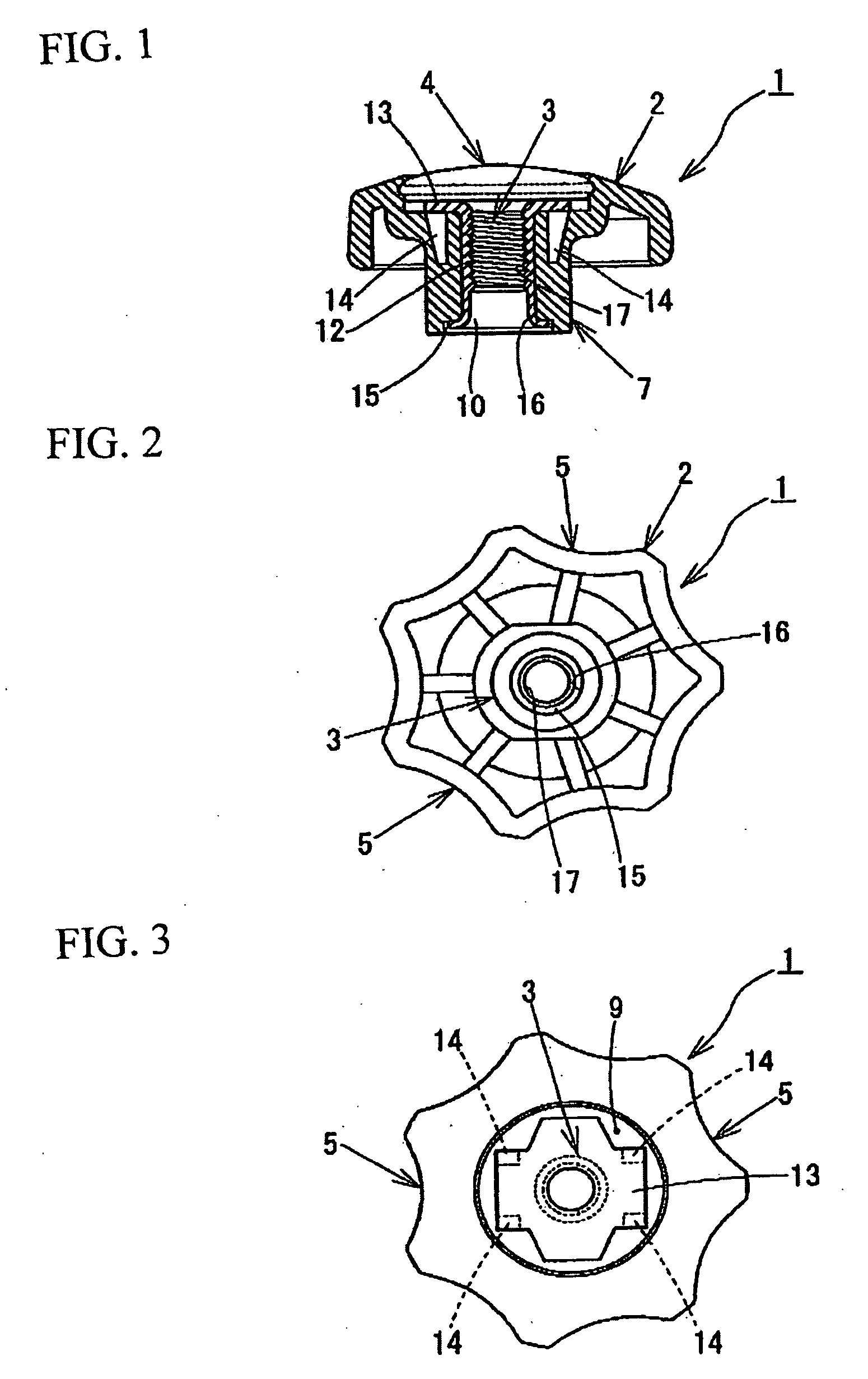
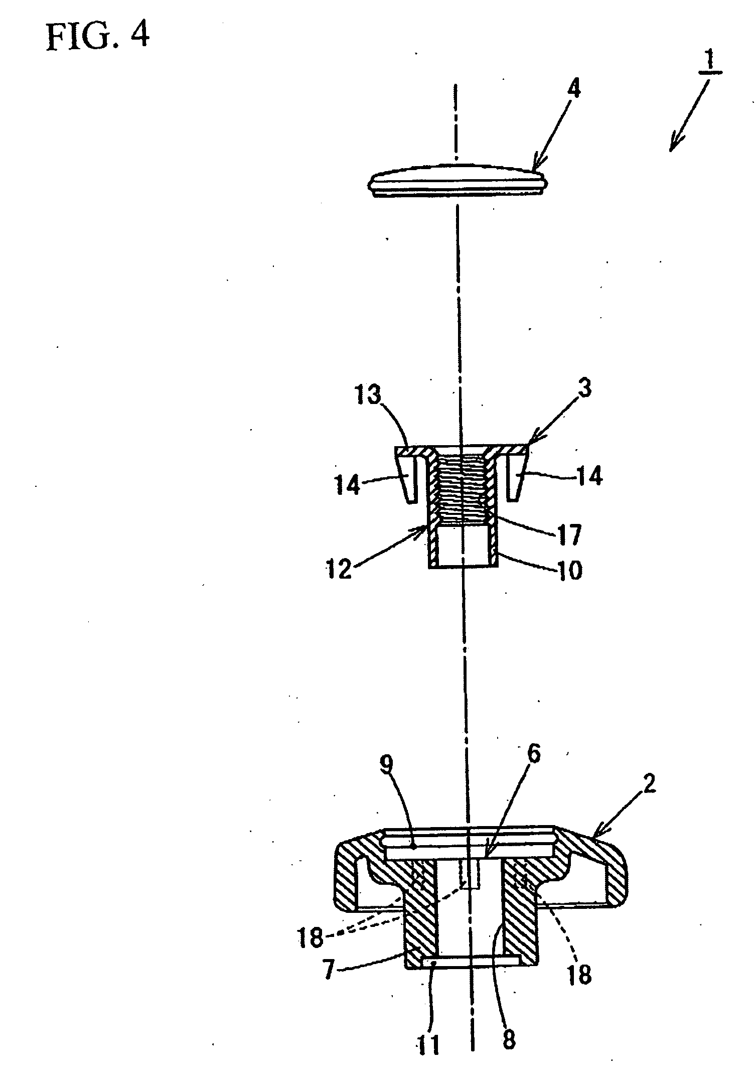
[0028]FIG. 1 illustrates a longitudinal cross section view of a nip for valve operation as an embodiment of a synthetic resin member having a metal female screw portion, in which it is used by being attached to an operation shaft of open / close valve (not illustrated in the drawings). FIG. 2 illustrates a bottom view of the nip for valve operation. FIG. 3 illustrates a plan view the nip for valve operation, in which the cap thereof is detached. FIG. 4 illustrates a plan view of a disassembled view the nip for valve operation, in which a part thereof is cut.
[0029]The nip 1 for valve operation has a body 2 made of a synthetic resin (i.e., a synthetic resin body), a screw formation portion 3 and cap 4 engaged with the body 2.
[0030]The body 2 has formed seven dimples 5 such that each draws a moderate arc on the outside of the body, and the upper portion of the body has swelled while the center thereof has a screw engagement portion 6 which is closed by cap 4.
[0031]The screw engagement por
example 2
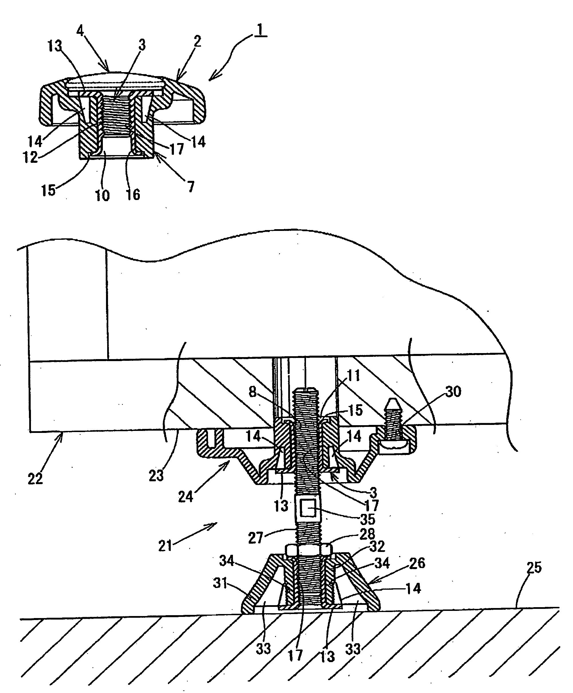
[0046]FIGS. 6 to 12 illustrate a synthetic resin member 21 having a metal female screw for adjusting the height or level of furniture or office automation devices (to-be-adjusted body). FIGS. 6 to 12 illustrates cross sectional views of use conditions.
[0047]The synthetic resin member 21 of the embodiment has an upper synthetic resin body 24, to be attached on a lower surface portion of furniture or office automation devices, a lower synthetic resin body 26 contacting the installment surface 25, screw bar 27 for space adjustment and lock nut 28 which are screw-engaged with both the upper and lower synthetic resin bodies 24, 25.
[0048]The upper synthetic resin body 24, as illustrated in FIGS. 6 to 9, forms attachment hole 30 at the hour corners of the square base 29, the attachment hole 30 attaching the upper synthetic resin body 24 to the lower surface portion 23 of furniture or office automation devices 22. In the center of the base 29, the screw portion engagement hole 8 penetrates, in
PUM
 Abstract
Description
Claims
Application Information
 - R&D Engineer
- R&D Manager
- IP Professional
- Industry Leading Data Capabilities
- Powerful AI technology
- Patent DNA Extraction
Browse by: Latest US Patents, China's latest patents, Technical Efficacy Thesaurus, Application Domain, Technology Topic.
© 2024 PatSnap. All rights reserved.Legal|Privacy policy|Modern Slavery Act Transparency Statement|Sitemap