Touch control apparatus of electronic musical instrument

Active Publication Date: 2009-09-24
YAMAHA CORP
View PDF5 Cites 10 Cited by
  • Summary
  • Abstract
  • Description
  • Claims
  • Application Information

AI Technical Summary

Benefits of technology

[0020]According to the present invention, the drive means is controlled such that the reaction force increases with increase in the differential acceleration signal of the performance operator during the initial period, and that the reaction force is g

Problems solved by technology

Therefore, there is a problem that the delay in the rising up of reaction force makes the player recognize the sense of touch immediately after th

Method used


Image

  • Touch control apparatus of electronic musical instrument
  • Touch control apparatus of electronic musical instrument
  • Touch control apparatus of electronic musical instrument

Examples


Embodiment Construction

1. Hardware Configuration of an Embodiment

1.1. Configuration of Keyboard Portion 10

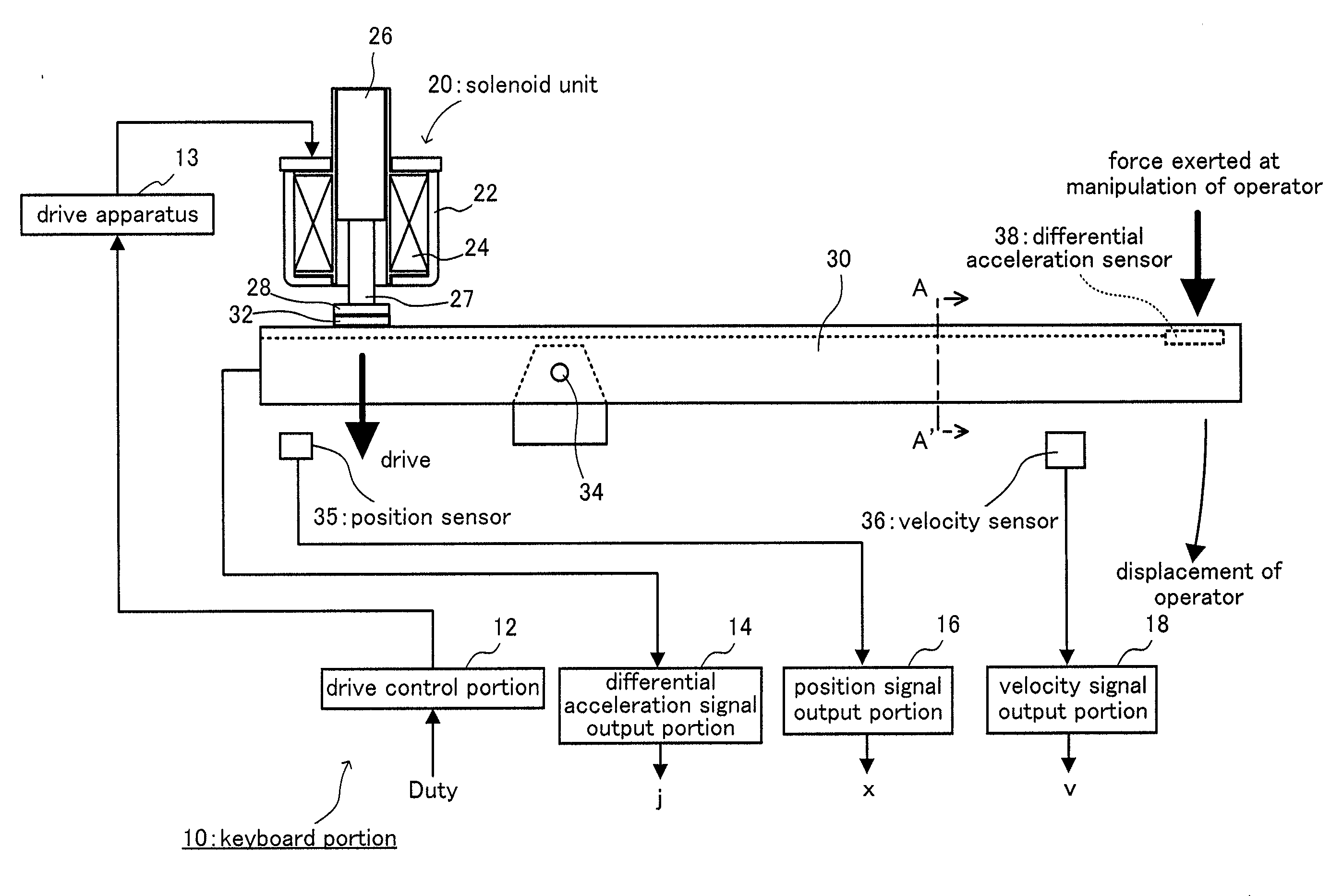
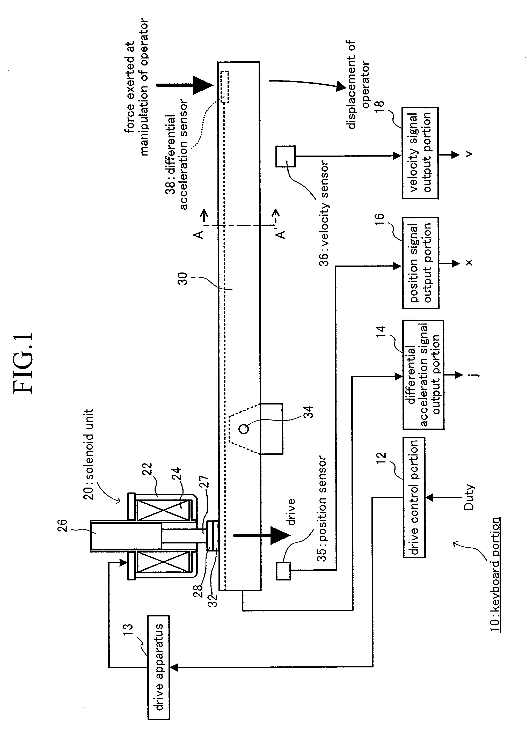
[0029]Next, configuration of a keyboard portion 10 of an electronic piano according to an embodiment of the present invention will now be described, referring to FIG. 1. Although the keyboard portion 10 is formed of a plurality of keys and their peripheral circuits, FIG. 1 shows the configuration of only one of the keys. A key 30 can freely pivot about a fulcrum 34. In this figure, the front of the key 30 is situated on the right side. More specifically, an end on the front side is to be depressed downward by a user. Above a rear end of the key 30, a solenoid unit 20 is provided. Inside the solenoid unit 20, a solenoid 24 is formed of a conducting wire wound to be approximately shaped like a cylinder. In addition, a yoke 22 is formed of a ferromagnet which covers the upper and lower end surfaces and the rim surface of the solenoid unit 20. The yoke 22 and the solenoid 24 form a stator of the solenoid uni


PUM


Abstract

In order to detect a state of a key 30, a differential acceleration sensor 38 is provided in addition to a common position sensor 35 and a velocity sensor 36. A reaction force applied by a solenoid unit 20 is determined on the basis of a function which monotonously increases with respect to a differential acceleration signal j in an initial period which is an early stage of depression of a key. After a lapse of the initial period, the reaction force is determined in accordance with velocity, acceleration and the like, referring to a table. As a result, the reaction force rises up rapidly when a key is depressed strongly.

Description


Claims


Application Information

Patent Timeline
Owner YAMAHA CORP
Why Eureka
Try Eureka