Method & device for enhancing aroma from beverage cup
a technology of aroma and beverage cup, which is applied in the field of beverage cup aroma enhancement methods and devices, can solve the problem of limiting the user's experience to inhaling the smell of already steeped grounds or leaves
- Summary
- Abstract
- Description
- Claims
- Application Information
AI Technical Summary
Benefits of technology
Problems solved by technology
Method used
Image

Examples
first embodiment
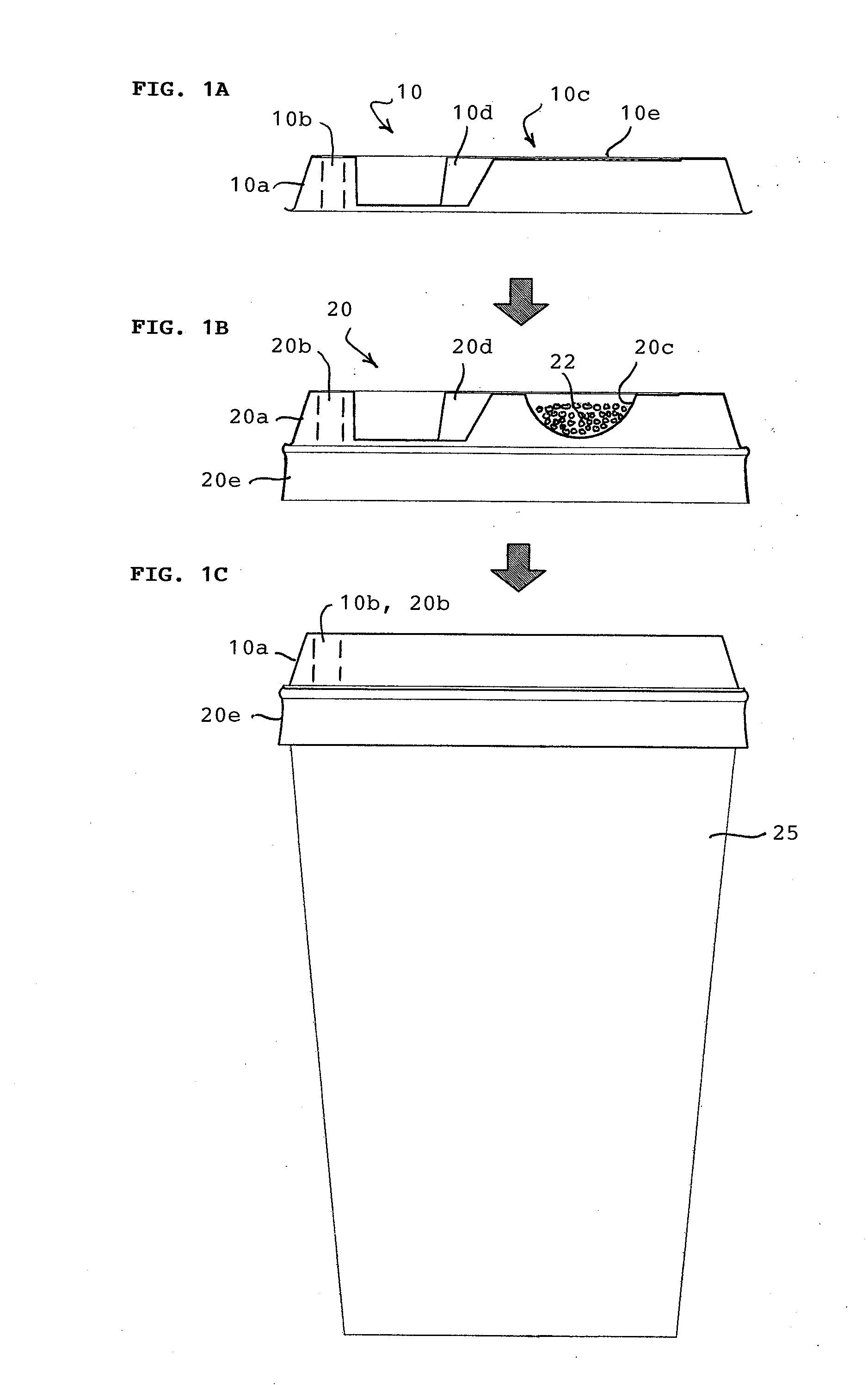
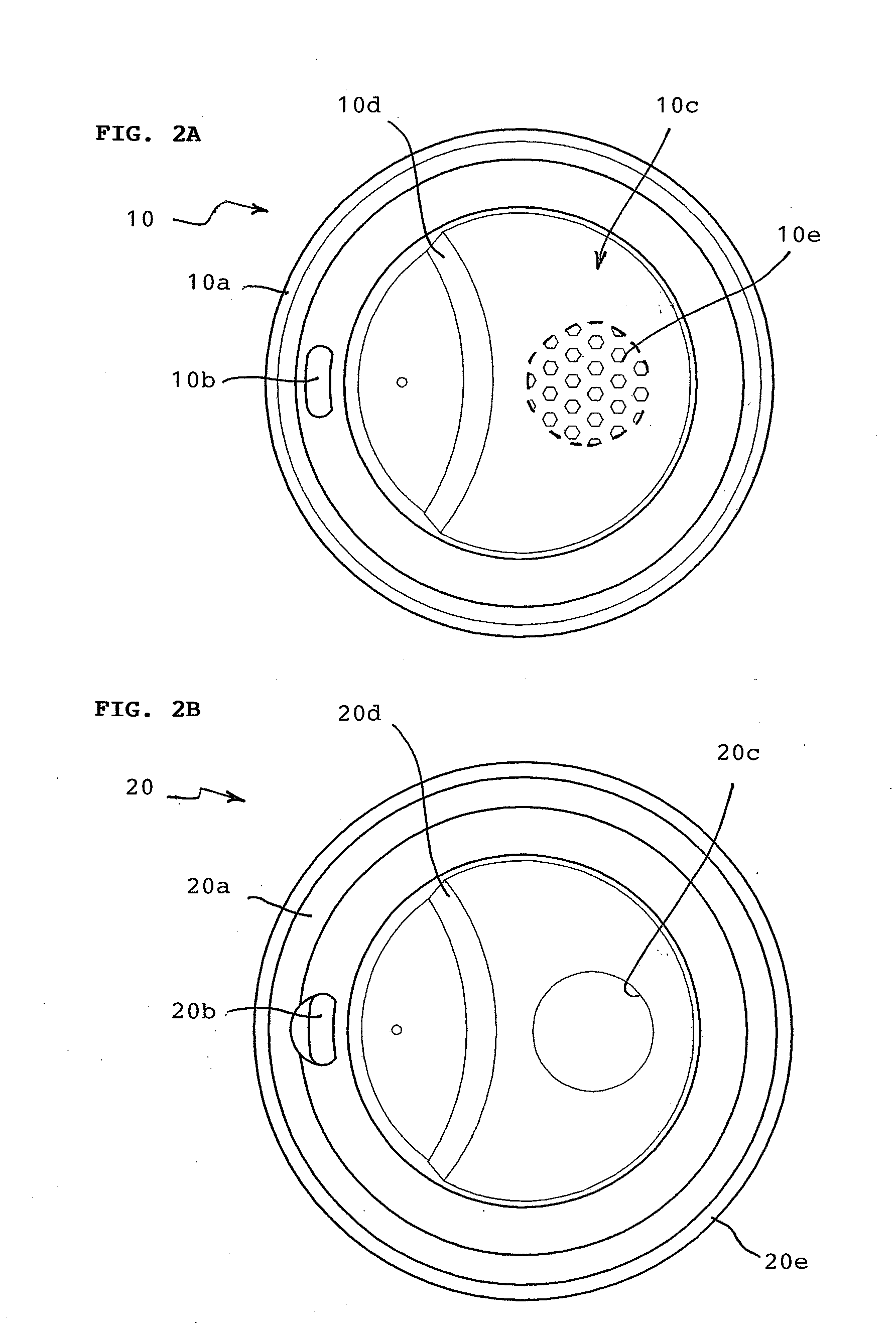
[0016]Referring to FIGS. 1A, 1B, and 1C, the aroma enhancing device has a receptacle member formed as a two-part lid for a cup including an outer receptacle cover 10 with annular walls 10a (with truncated cone cross-section) that fit onto similar annular walls 20a of an inner receptacle body 20. The outer receptacle cover 10 has a standard type of crescent-shaped sip hole 10b formed through the cover on one side (left side of the figure) and a covering portion 10c on an opposite side (right side of the figure) of the cover. The inner receptacle body has a matching sip hole 20b similarly formed through it on one side and a receptacle pocket 20c on an opposite side therefrom. The outer receptacle cover 10 is shaped with an upper surface contour similar to that of the inner receptacle body 20 so that the two parts can nest tightly together when positioned one on top of the other. The receptacle pocket is sized to hold a small amount of fresh beverage material 22, such as fresh coffee grou
second embodiment
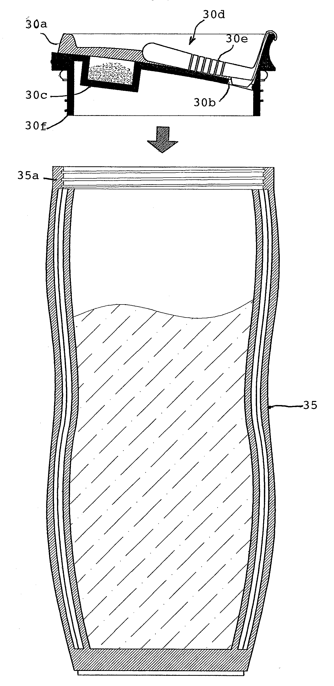
[0022]As shown in FIGS. 3A, 3B, and 3C, the aroma enhancing device has a plastic top 30 formed with annular walls 30a, a sip hole 30b, a receptacle pocket 30c, and a hinged cover member 30d. The hinged cover member 30d has an area perforated with perforation holes or a screen 30e for releasing the aroma of fresh beverage material held in the receptacle pocket 30c. In FIG. 3A, the hinged cover member 30d is on the side covering the sip hole 30b and exposing the receptacle pocket 30c so that a sample of fresh beverage material 32 can be filled in. Shown in side view in FIG. 3B, taken along view lines B-B in FIG. 3A, the plastic top 30 is attached to the top of a plastic beverage cup 35 by a threaded lower skirt 30f which mates with a threaded rim 35a of the cup 35. The fitted plastic top can thus be screwed into the threaded rim of the cup to cover the cup after brewed beverage has been poured in.
[0023]A sample of fresh beverage material can be placed in the receptacle pocket 30c when th
third embodiment
[0024]As shown in FIGS. 5A to 5E, the aroma enhancing device is formed as a clip-on container attachment 50 to a standard shaped mug for drinking hot beverages. It has a container body 50a covered by a screen top 50b and a flexible spring-type clasp 50c for attaching onto the rim of the mug. The screen top 50b has a swivel locking device 50d that can be unlocked for loading a small sample of fresh beverage material into the container body 50a, and locked to retain the screen top 50b in its cover position over the container body, as illustrated in FIGS. 5B to 5E. The container attachment is mounted by the spring clasp 50c onto the rim of the mug in a position of about 90 degrees from the mug handle, so that as the user sips liquid beverage from the mug at an opposite side from the attachment position (270 degrees), the user's nose is in proximity to the container to smell the aroma of the fresh beverage material in the container.
[0025]In summary, the aroma-enhancing method and device se
PUM
 Abstract
Description
Claims
Application Information
 - R&D Engineer
- R&D Manager
- IP Professional
- Industry Leading Data Capabilities
- Powerful AI technology
- Patent DNA Extraction
Browse by: Latest US Patents, China's latest patents, Technical Efficacy Thesaurus, Application Domain, Technology Topic.
© 2024 PatSnap. All rights reserved.Legal|Privacy policy|Modern Slavery Act Transparency Statement|Sitemap