Coupling for Injection Devices

Inactive Publication Date: 2009-10-08
NOVO NORDISK AS
View PDF3 Cites 25 Cited by
  • Summary
  • Abstract
  • Description
  • Claims
  • Application Information

AI Technical Summary

Problems solved by technology

This however can result in some slack being intr

Method used


Image

  • Coupling for Injection Devices
  • Coupling for Injection Devices
  • Coupling for Injection Devices

Examples


Embodiment Construction

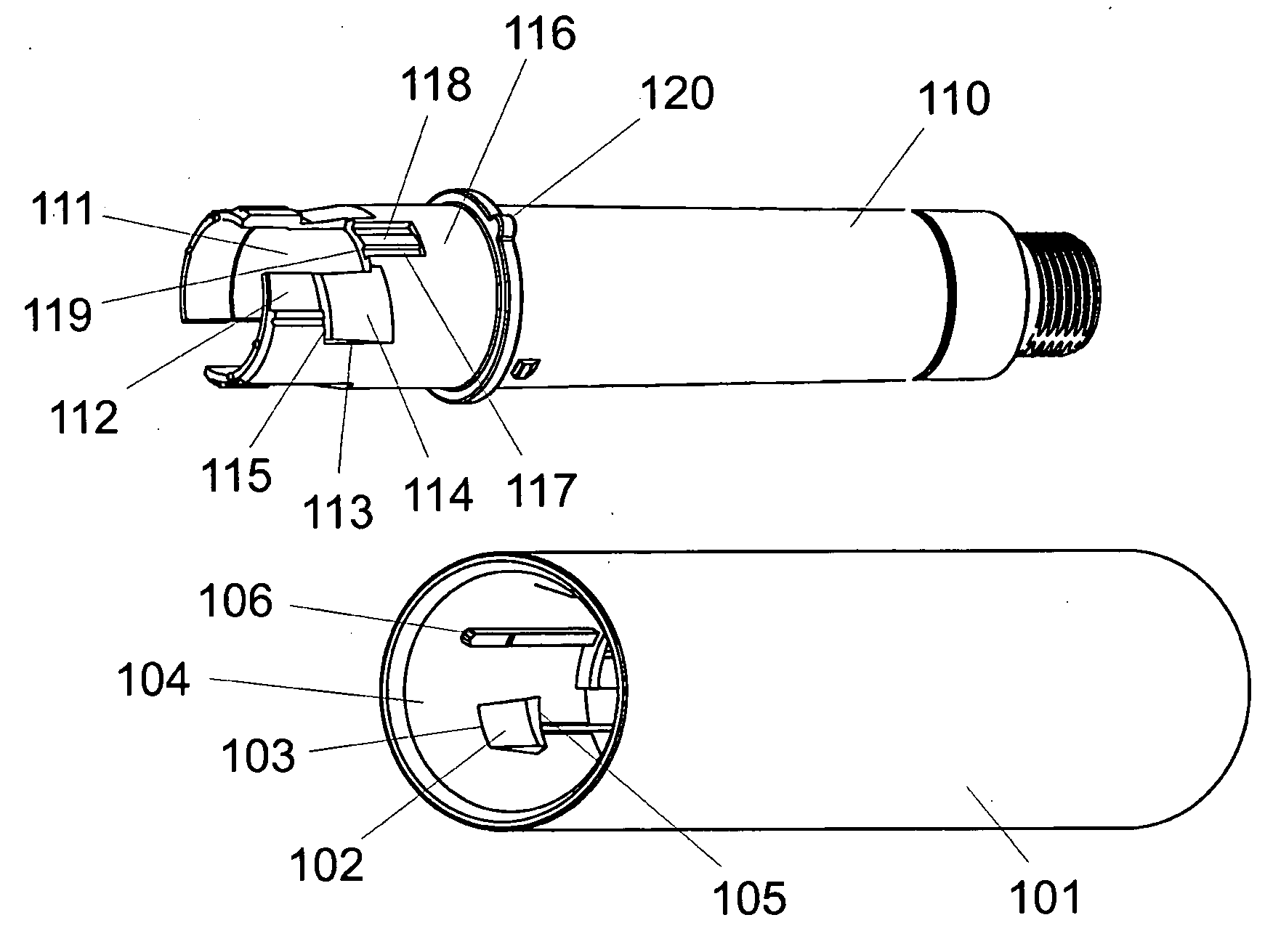
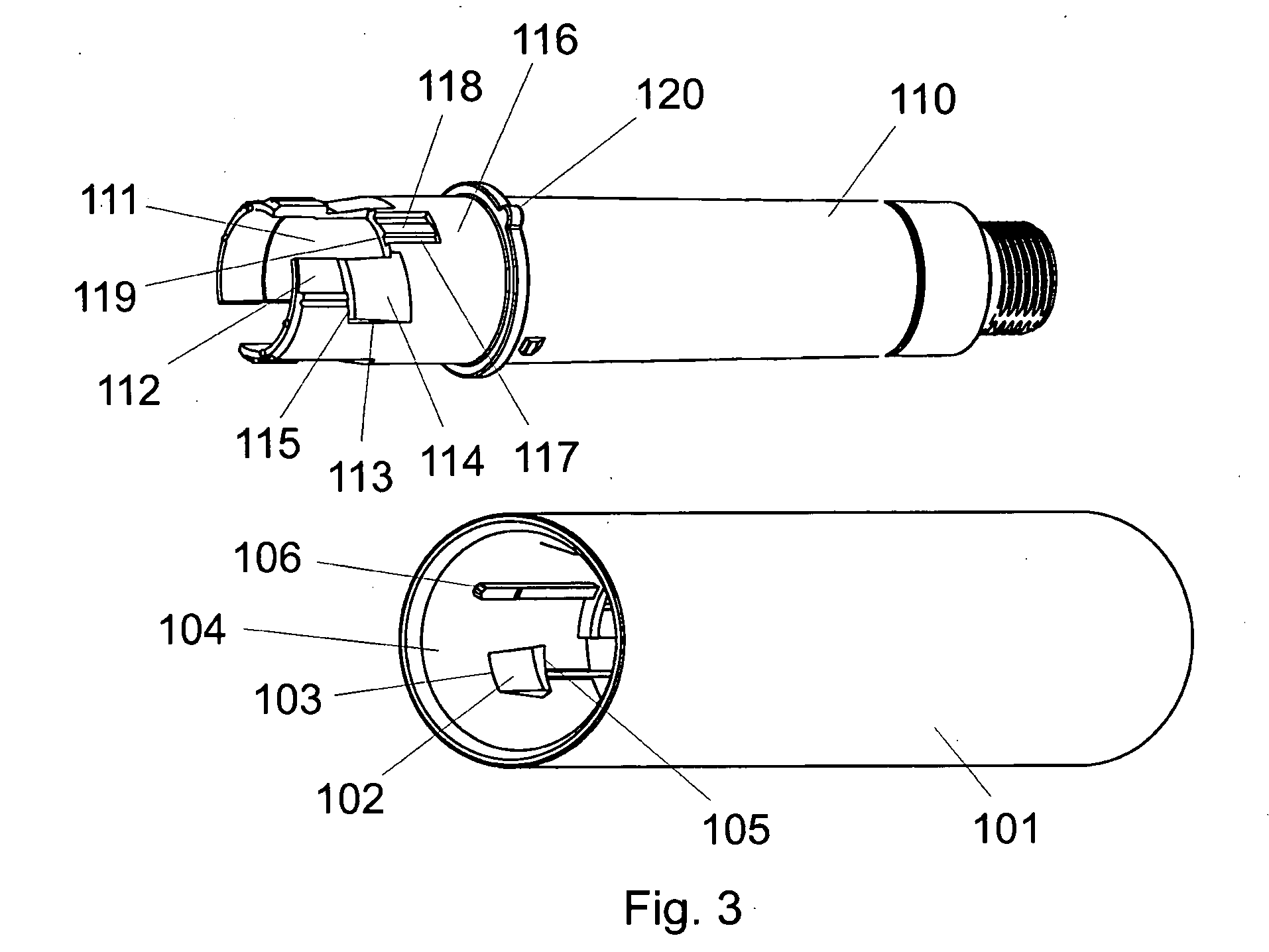
[0008]It is an object of the present invention to provide an irreversible mechanical locking that does not introduce slack between the parts locked together.

[0009]A bayonet coupling as the one known e.g. from WO 99 / 16487 has the advantage that the two elements is pressed together when the two parts are rotated relatively due to the angle of the protrusion and the bayonet thread.

[0010]Combining such bayonet coupling with an irreversible mechanical lock locking the parts together makes the solution very attractive to prefilled injection devices due to the fact that the press fitting of the two elements can reduce the slack occurring due to the injection moulding process involved in producing the various parts. The mechanical lock can be formed such that it locks into its locking position when the two elements are sufficiently pressed together by the bayonet coupling. In this way the mechanical slack can be reduced or even avoided.

[0011]The bayonet coupling is provided with a click-lock


PUM


Abstract

The present invention concerns a prefilled injection device having a container and a dose setting mechanism encapsulated inside the housing. The housing is made from two parts which are locked together by a bayonet coupling: In addition to the bayonet coupling, the two parts are also provided with irreversible locking means locking the two parts permanently together.

Description


Claims


Application Information

Patent Timeline
Owner NOVO NORDISK AS
Why Eureka
Try Eureka