Backlight unit
a backlight unit and backlight technology, applied in the field of backlight units, can solve the problems of reducing the uniformity of linear optical sources, reducing so as to reduce the unevenness of linear light sources, reduce the light condensing function, and advance the light diffusing function
- Summary
- Abstract
- Description
- Claims
- Application Information
AI Technical Summary
Benefits of technology
Problems solved by technology
Method used
Image

Examples
first embodiment
Positional Relation Between Linear Light Source and Optical Functional Sheet in First Embodiment
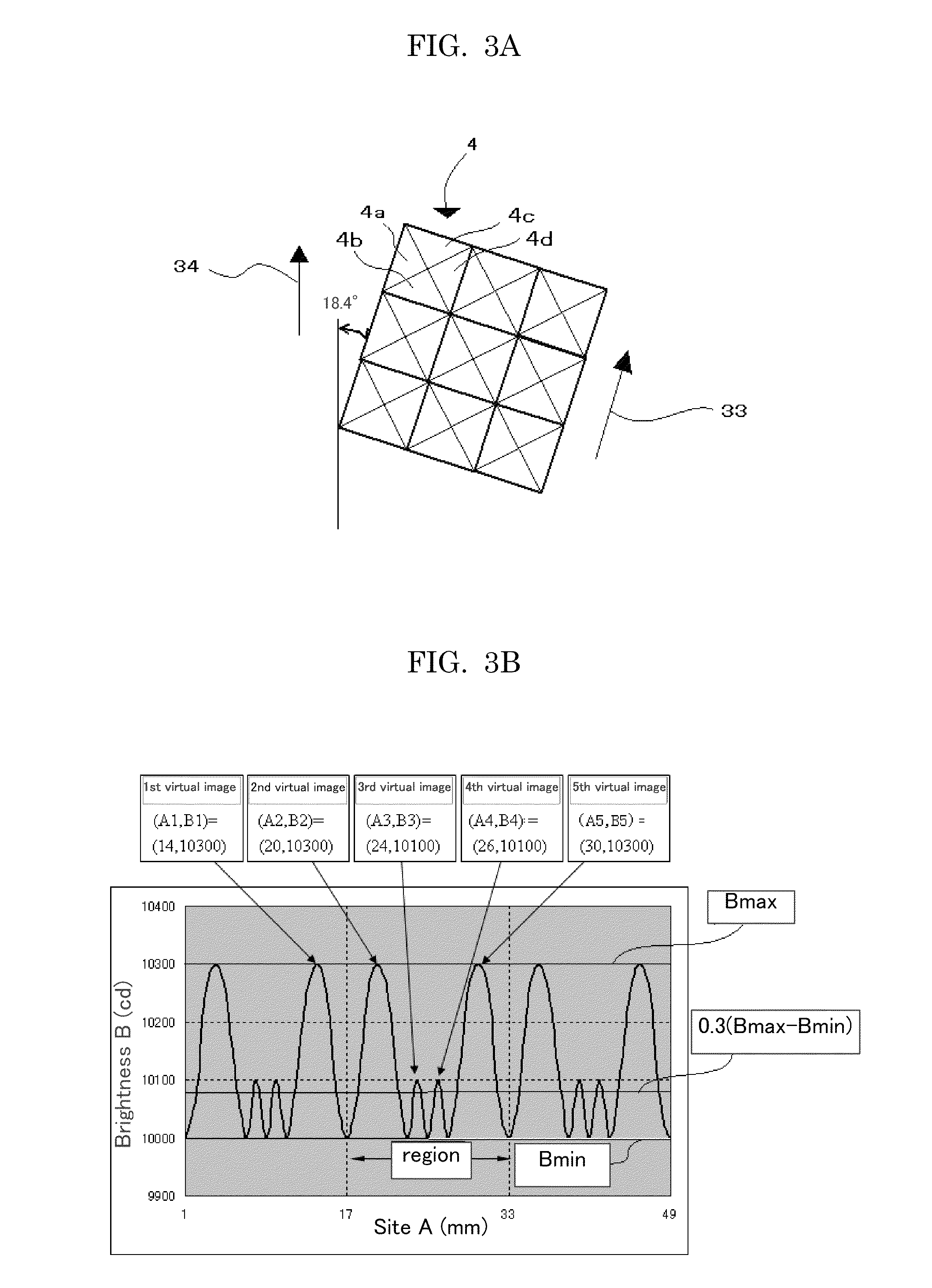
[0174]In cases where the shape of prisms 4 of the optical functional sheet 1 is a regular four-sided pyramid of concave or convex, as shown in FIG. 3A, the aligning direction (arrow 33) of the prisms 4 is inclined against the direction (arrow 34) of the linear light source at an angle of 18.4° (=tan−1 ⅓), which being theoretically most desirable, so that the brightnesses of virtual images derived from a linear light source are approximately the same over the optical functional sheet 1 and the distances of adjacent virtual images derived from a linear light source are approximately the same over the optical functional sheet 1, and thus the brightnesses of virtual images derived from plural linear light sources are approximately the same over the optical functional sheet 1 and the distances of adjacent virtual images derived from plural linear light sources are approximately the same over the
second embodiment
Positional Relation Between Linear Light Source and Optical Functional Sheet in Second Embodiment
[0209]FIG. 8 is a view that explains a positional relation between the optical functional sheet shown in FIG. 1 and linear light sources.
[0210]In the positional relation of the optical functional sheet 1 and the linear light source 30 shown in FIG. 8, f(p) is a distance between a nodal line 40 and a virtual image that is nearest to the nodal line; in which the nodal line is one between a flat surface, which containing a linear light source (e.g., linear light source 30A) among the plural linear light sources and being perpendicular to the optical functional sheet 1, and a flat surface, which containing the optical functional sheet 1, and the nodal line is a projected line 40 of a linear light source (e.g., linear light source 30A) among the plural linear light sources onto the optical functional sheet 1; and the virtual image is one (e.g., virtual image 32A) that is nearest to the nodal lin
example 1-a
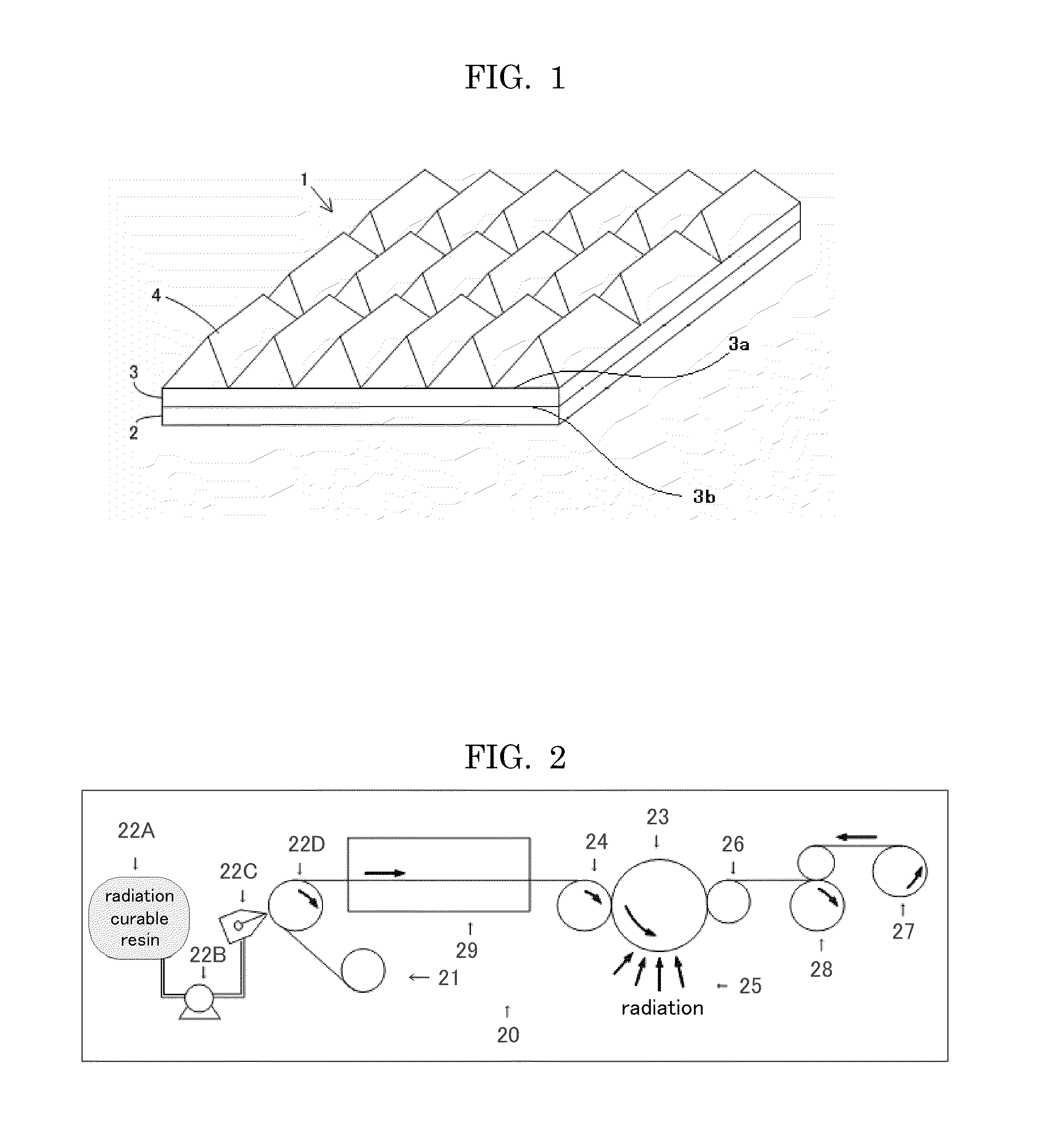
[0235]A sheet of 200 μm thick was formed by extrusion molding from a polycarbonate resin (refractive index: 1.59, by Mitsubishi Chemical Co.); then the sheet was heat-pressed by a mold having a convex regular four-sided pyramid pattern of 50 μm in bottom width and 25 μm in height under a condition of 200° C., 2 MPa, and 10 minutes, thereby to prepare an optical functional sheet of 17 cm square having a transferred pattern of concave regular four-sided pyramid (FIG. 3A). From the resulting optical functional sheet, cold cathode tubes of 3 mm in diameter as plural linear light sources aligned in parallel, a reflective plate (light box) to reflect a light from the cold cathode tubes, and a diffusing sheet (D121Z, by Tsujiden Co.) disposed between the cold cathode tubes and the optical functional sheet (FIG. 15), a backlight unit was prepared in a way that the optical functional sheet was disposed such that the aligning direction of prisms (regular four-sided pyramid) of the optical functi
PUM
 Abstract
Description
Claims
Application Information
 - R&D Engineer
- R&D Manager
- IP Professional
- Industry Leading Data Capabilities
- Powerful AI technology
- Patent DNA Extraction
Browse by: Latest US Patents, China's latest patents, Technical Efficacy Thesaurus, Application Domain, Technology Topic.
© 2024 PatSnap. All rights reserved.Legal|Privacy policy|Modern Slavery Act Transparency Statement|Sitemap