Upright type vacuum cleaner

a vacuum cleaner and upright technology, applied in the direction of vacuum cleaners, cleaning filter means, domestic applications, etc., can solve the problems of inconvenient use, lack of balance, and the vacuum cleaner may not be easily balanced while moving, so as to increase the vacuum pressure

Inactive Publication Date: 2010-10-28
SAMSUNG ELECTRONICS CO LTD
View PDF35 Cites 6 Cited by
  • Summary
  • Abstract
  • Description
  • Claims
  • Application Information

AI Technical Summary

Benefits of technology

The inventor describes how it can help prevent damage caused by excessive negative pressures on fans during operation. This happens when there are too many things happening inside or outside that could cause problems with other components within the system's electronic devices like sensors.

Problems solved by technology

Technics: ULVAC® brand suction cleaners have long been known for their ability to remove small debris without being affected negatively or causing damage due to excessive heat buildup caused by continuous use of electrical current. However, these devices require frequent battery replacement because they cannot maintain balance when moved around freely. Additionally, users often want more space inside them than what can fit into this limited area.

Method used


Image

  • Upright type vacuum cleaner
  • Upright type vacuum cleaner
  • Upright type vacuum cleaner

Examples


Embodiment Construction

[0034]The following detailed description is provided to assist the reader in gaining a comprehensive understanding of the methods, apparatuses, and / or systems described herein. Accordingly, various changes, modifications, and equivalents of the systems, apparatuses, and / or methods described herein will be suggested to those of ordinary skill in the art. Also, descriptions of well-known functions and constructions may be omitted for increased clarity and conciseness.

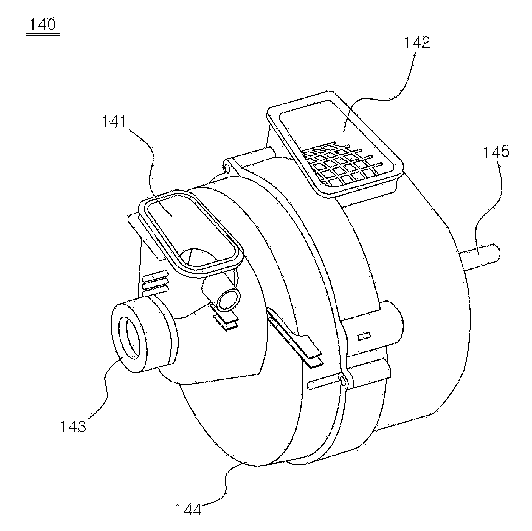
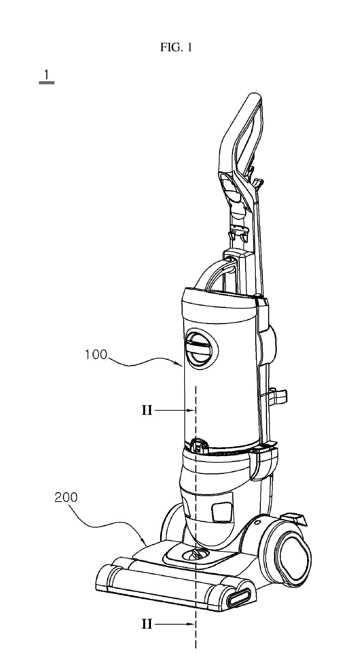
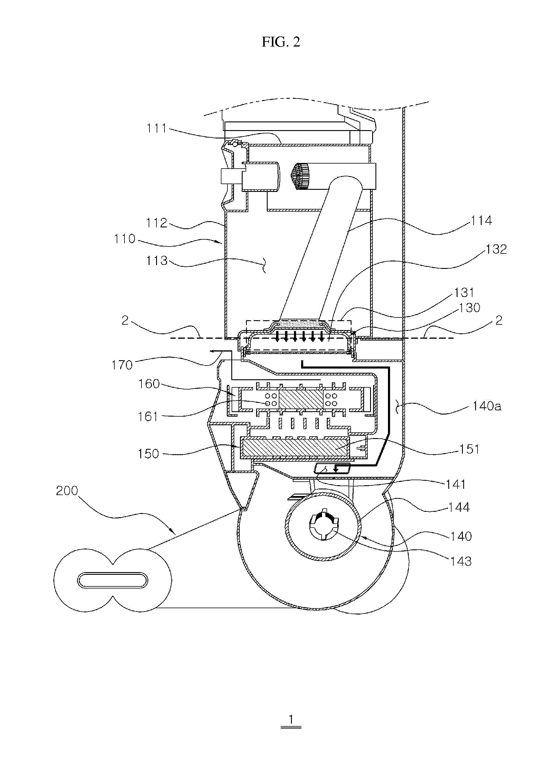
[0035]FIG. 1 illustrates an example of an upright type vacuum cleaner (also referred to as ‘vacuum cleaner’). FIG. 2 illustrates a partial cross section view taken on line II-II, showing an example of a lower area of the vacuum cleaner of FIG. 1, including an arrangement of a pre-filter unit, a post-filter unit, a cord reel unit, and a fan motor unit Referring to the examples illustrated in FIG. 1 and FIG. 2, the vacuum cleaner 1 includes a main body 100 having a hose nozzle (not illustrated) to clean narrow areas, and a


PUM


Abstract

An upright type vacuum cleaner is provided. The upright type vacuum cleaner comprising a brush assembly and a main body rotatably mounted on the brush assembly, wherein the main body has a dust collecting apparatus, a pre-filter unit, a cord reel unit and a fan motor unit, wherein the fan motor unit is installed on a lower portion of the main body, and the cord reel unit is arranged between the pre-filter unit and the fan motor unit such that the discharging air out of the fan motor unit is discharged through the cord reel unit.

Description


Claims


Application Information

Patent Timeline
Owner SAMSUNG ELECTRONICS CO LTD
Why Eureka
Try Eureka