Chassis for nozzle with air guiding element

A technology of air guiding components and chassis, which is applied in the direction of suction nozzles, household appliances, applications, etc. It can solve the problems of pushing the suction nozzle, getting stuck, and the suction nozzle can only move by jumping, so as to avoid sticking and vacuuming The effect of effect promotion

Active Publication Date: 2018-07-20
VORWERK & CO INTERHOLDING GMBH
View PDF13 Cites 0 Cited by
  • Summary
  • Abstract
  • Description
  • Claims
  • Application Information

AI Technical Summary

Benefits of technology

This patented technology allows for an improved design for a vacuum cleaner's suction system. It achieves these technical improvements without causing problems such as clogging or getting stuck due to debris being collected during use.

Problems solved by technology

This technical problem addressed in this patents relates to improving the design of suctions without causing damage to sensitive areas like furniture surfaces while still effectively removing debris (such as small pieces) found between them.

Method used


Image

  • Chassis for nozzle with air guiding element
  • Chassis for nozzle with air guiding element
  • Chassis for nozzle with air guiding element

Examples


Embodiment Construction

[0035] In the following description of the different exemplary embodiments according to the invention, components and elements which have the same function and mode of operation are marked with the same reference numerals, even if these components and elements have different dimensions in the different exemplary embodiments or shape.

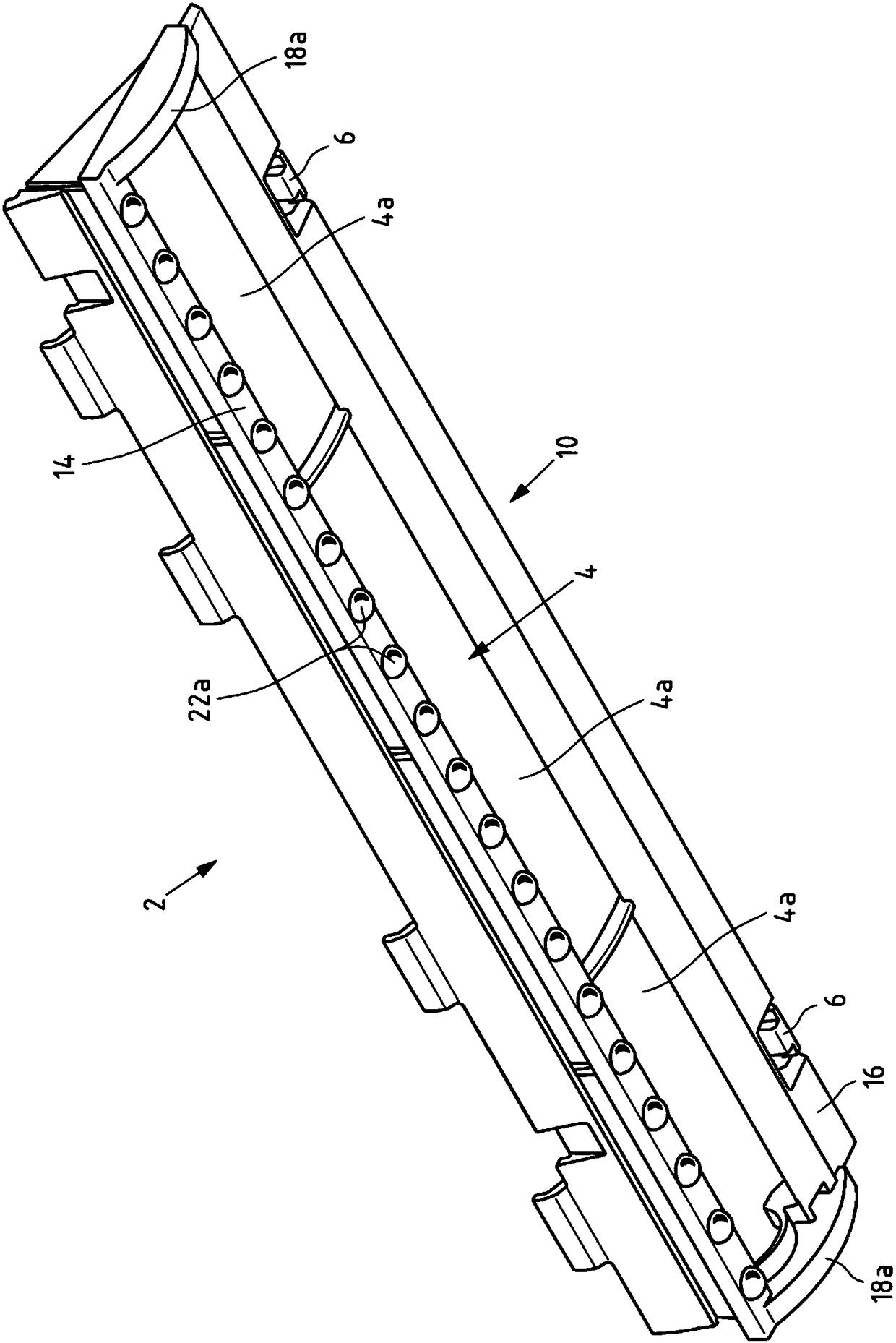
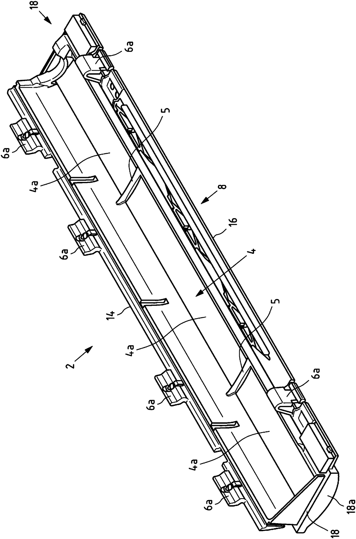
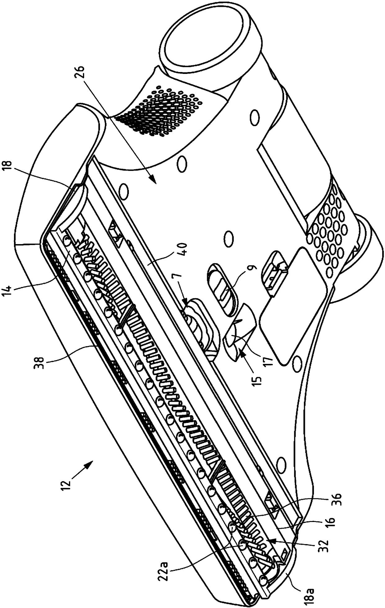
[0036] figure 1 A perspective view obliquely below is shown of a first exemplary embodiment of a chassis 2 for suction nozzles 12 according to the invention. The bottom surface 10 of the undercarriage 2 is thus shown in this view. Here, the undercarriage 2 has a suction opening 4 which is delimited by and thus defined by a front edge 14 , a rear edge 16 and two side edges 18 . The edges 14 , 16 and 18 not only delimit the suction opening 4 but also form planar sections of the chassis 2 . Additionally, the side edges 18 are formed as bearing blocks 18a.

[0037] Attached on the upper side of the front edge 14 and the rear edge 16 are connecting


PUM


Abstract

The invention relates to a chassis for a nozzle having at least one suction opening (4), an upper surface (8) and a bottom surface (10), wherein the front edge (14) and the rear edge of the chassis (2) and the side edge (18) defines the suction port (4). This technical problem of solving the problems known in the prior art and realizing a comfortable running process of the nozzle on the carpet floor with sufficient cleaning effect is solved by forming on the bottom surface of the side edge (18). At least one support block (18a) forms an air guiding element (22) on the bottom surface of the front edge (14) and the air guiding element (22) is formed in the form of a raised portion (22a) spaced apart from each other. Furthermore, this technical problem is solved by a suction nozzle (12) having a chassis (2) according to the invention and by a vacuum cleaner (44) having a nozzle (12) according to the invention.

Description


Claims


Application Information

Patent Timeline
Owner VORWERK & CO INTERHOLDING GMBH
Why Eureka
Try Eureka