Stent graft

Active Publication Date: 2010-11-11
COOK MEDICAL TECH LLC
View PDF13 Cites 10 Cited by
  • Summary
  • Abstract
  • Description
  • Claims
  • Application Information

AI Technical Summary

Benefits of technology

[0012]An advantage of this configuration is that is satisfies several design constraints. For example, it provides a flexible interconnection between the end stent and the next stent to enable the stent graft to more closely follow the inner curve of the aortic arch, and thus a more precisely aligned location of the stent graft in the body vessel. Furthermore, the configuration permits the stent graft, and in particular its proximal end, to be folded into a compact arrangement when compressed. This can be attributed, at least in part, to the absence of graft material where it

Problems solved by technology

A problem with the deployment of stent grafts in the aortic arch is that a satisfactory engagement against the inte

Method used


Image

  • Stent graft
  • Stent graft
  • Stent graft

Examples


Embodiment Construction

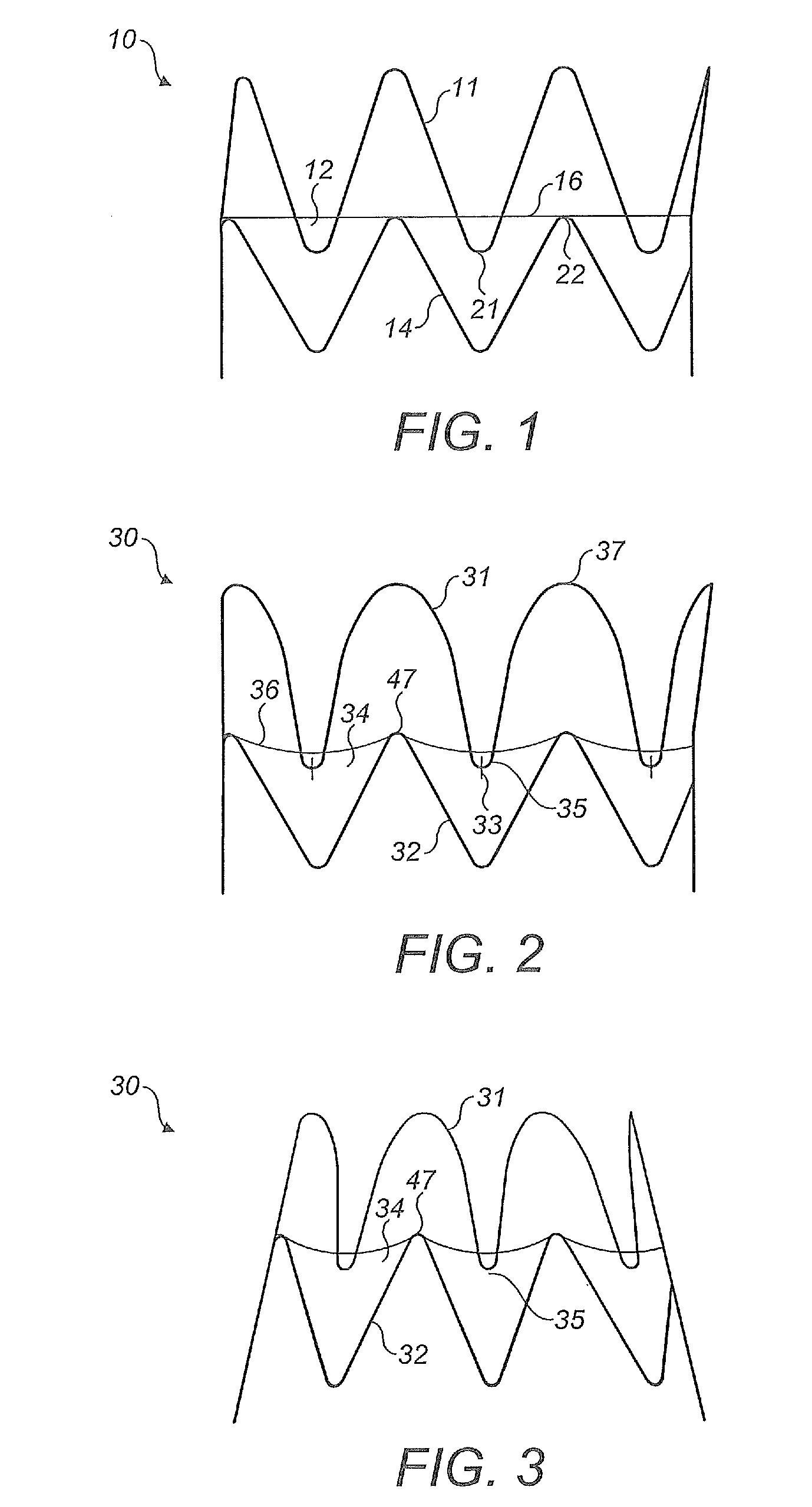
[0027]Referring to the drawings, FIG. 1 shows a stent graft 10 in accordance with the prior art. A proximal end stent 11 is substantially bare, that is only a relatively small part of the stent is covered with graft material 12. For most of its length, the wire forming stent 11 has no graft material on either side; at intervals, relatively short lengths of the wire have graft material on all sides. The next stent 14 is completely covered by the graft material. Viewed in the sideways or radial direction of the Figure, the end 16 of the graft material is a straight line. The graft material 12 and the stent members 11, 14 attached thereto are substantially circular in cross-section.

[0028]As seen in FIG. 1, the distal peaks 21 of stent 11 overlap the proximal peaks 22 of the next stent 12 in the longitudinal direction. The peaks 21 and 22 alternate in regular manner around the periphery of the stent graft.

[0029]Problems can arise when compressing the stent graft 10 for passage through a re


PUM

PropertyMeasurementUnit
Lengthaaaaaaaaaa
Lengthaaaaaaaaaa
Lengthaaaaaaaaaa

Abstract

A stent graft 30 has a bare end stent 31 which partially overlaps the next stent 32 with the end 36 of the graft material 34 being shaped to follow the distal peaks 35 of the end stent and the proximal peaks 47 of the next stent. The proximal peaks 37 of the end stent have a greater radius of curvature than the distal peaks 35 of the end stent.

Description


Claims


Application Information

Patent Timeline
Owner COOK MEDICAL TECH LLC
Why Eureka
Try Eureka